
0 Preface
With the development of social economy and science and technology, the problem of energy loss has become increasingly prominent. The intelligent control of lighting in indoor public places such as Chinese companies and even corporate enterprises is relatively lacking and imperfect. Most of them are traditional manual management, which causes a lot of unnecessary energy waste and economic loss. This waste is contrary to today's energy-saving concept [ 1-3]. In addition, with the popularity of computer technology and the increasing degree of automation, measures to automatically control lighting are still very necessary to implement. At present, there are products using sound control, light control and even temperature control to achieve this purpose, but they all have their own shortcomings, which are easily affected by noise, ambient temperature and other factors. Turning on causes waste of energy. In this regard, the system is mainly based on the principle of infrared sensing, using a single-chip microcomputer to record the number of indoors detected by the dual-parallel infrared detector [4], and adding an ambient light detection module to activate the LED when the indoor light is dark and there is a person in the room. Energy-saving lighting devices to achieve the goal of combining energy saving and convenience.
1 system overall design
The system is mainly composed of four modules: infrared detection module, ambient brightness detection module, single chip module and LED lighting module. Using two parallel active pyroelectric infrared detectors to detect the number of indoors, the ambient brightness detection module detects the intensity of the indoor light, and then transmits the detection data to the control core—80C51 microcontroller, which will control whether the LED lighting device is processed according to the processing result. Open.
1.1 Infrared detection module
The active infrared detector is composed of an infrared emitter and an infrared receiver. The infrared emitter in the device is an infrared LED, and the receiver is a phototransistor. The schematic diagram of the infrared detection circuit is shown in FIG. When no one passes the detector, U2:A's 1 pin outputs a low level; when someone passes, U2:A's 1 pin outputs a high level [5]. The whole system is used by two active infrared detectors. In one infrared detection circuit, the pin 1 of the amplifier U2:A is connected to the pin of P1.0 of the 80C51 MCU, and the pin 1 of the other amplifier U2:A is connected. The pin of the P1.1 of the 80C51 microcontroller.

Figure 1 infrared detector circuit
1.2 MCU module
In the whole system, the purpose of combining the two detectors is to judge whether the person passes in or out through the detector, and records the number of people in the single-chip microcomputer [6-7]. The detector 1 is installed in the door, and the detector 2 is installed outside the door. When the person passes the detector 1 and then passes through the detector 2, it means that someone goes out, and the counting procedure inside the single chip microcomputer is automatically reduced by 1; When the detector 2 passes the detector 1, it indicates that someone is coming in, and the counting program inside the microcontroller is automatically incremented by one. When the data in the counter is 0, it means that no one in the room, the single chip will not turn on the lighting circuit; when the data in the counter is greater than or equal to 1, it means that there is someone in the room, the single chip will turn on the lighting circuit at this time. There is also a prerequisite for turning on the lighting circuit—the control of the ambient brightness module. When the external ambient light is relatively strong, even though some people in the room have no need to turn on the lighting circuit at this time [8-9].
1.3 Ambient brightness detection module
The ambient brightness detection module is mainly used to sense the intensity of external light to avoid unnecessary waste. As shown in Fig. 2 [10], the photoresistor RV2 is used instead of the photoresistor, and the photoresistor gradually decreases in resistance as the light is increased. When the external light is strong, the pin 1 of the LM358 outputs a low level; when the external light is weak, the pin 1 of the LM358 outputs a high level and is then input to the P1.2 pin of the microcontroller.

Figure 2 Ambient brightness detection circuit
1.4 Lighting circuit module
The lighting circuit is actually very simple, directly connected to the P2.0 pin of the microcontroller to connect the LED lighting, the connection mode can be connected in series or in parallel according to the actual situation. The opening of the circuit is mainly controlled by the single-chip microcomputer. The single-chip microcomputer will turn on the lighting circuit when its P2.0 pin is high level and the data in the counter is not 0, indicating that the lighting circuit is turned on when the light is weak and there is someone in the room. .
The integration of the above four modules is the entire automatic lighting system, as shown in Figure 3.

Figure 3 overall circuit
2 Experimental simulation and analysis of results
The system design mainly uses the keiluv3 single-chip design software and the proteus circuit processing software. The key of the whole system lies in the control of the single-chip program. The program flow chart is shown in Figure 4.
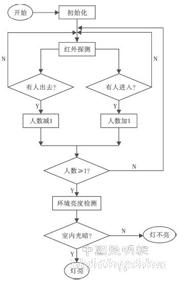
Figure 4 circuit flow
In software simulation, only the input and output pins of the MCU need to be connected, but in the actual circuit connection, the crystal, power, reset and other pins need to be connected to the circuit. Because it is analog, the detector sensing module and the environmental module can be simplified. The P1.0 and P1.1 pins are connected to the simplified circuit of the infrared detection module, while the P1.2 pin is connected to the ambient brightness. The simplified circuit of the detection module is shown in Figure 5.
For a single-chip microcomputer, when the potential of the P1 pin is greater than 2.3V, it can be judged as a high level and set to 1. In the simulation, the diode is reversed by the unidirectional conduction characteristic of the diode. In the off state, the potential at P1 is +5V, so P1.0, P1.1, and P1.2 of the single-chip microcomputer are all set to 1, indicating that the light is dark at this time and there is someone in the room, and the single-chip microcomputer will control the opening of the lighting circuit.