
In order to control fuel consumption, many car manufacturers have implemented "start and stop" functions in the next generation of cars, and a large number of such cars have begun to take the road. These systems shut down the engine when the car is stopped, and when the foot moves from the brake pedal to the accelerator pedal—or automatically re-start the engine when the clutch pedal is released using the manual gear to re-energize. This feature is very helpful in reducing fuel consumption during peak hours of city travel and stop-and-go.
However, this system also presents some unique engineering challenges to automotive electronics because the battery voltage can drop to 6.0V or less when the engine is restarted. In addition, typical electronic modules include a reverse polarity diode that protects the vehicle's circuitry when the car is lined up and accidentally reverses the line. This diode will reduce the battery voltage by another 0.7V, so the voltage available for downstream circuits is only 5.3V or lower. Since many modules still require a 5V power supply, there is basically no margin and it is difficult to ensure that the circuit works properly.
Boost power supply
One method is to boost the power supply, that is, input a lower voltage and output a higher voltage. At present, many suppliers use some type of boost power supply at the front end of the electronic module, so that the electronic module can work normally even under the step-down condition caused by the start-stop system.
As with most engineering problems, there are many ways to solve problems. If the battery voltage at the input only drops to 6V, then the simplest and simplest solution is to find a low-dropout linear regulator that works with a dropout voltage of less than 0.3V. This method is suitable for modules with lower current requirements, but this method is not suitable for modules with high current requirements.
Another method is to replace the standard PN junction diode for reverse polarity protection of the front-end battery with a Schottky diode or a P-channel MOSFET. The forward voltage drop of a Schottky diode is about half that of a standard rectifier, so it can increase the differential margin of a few tenths of a volt. Switching to a Schottky diode is fairly straightforward because it can be mounted directly on the same PCB pad as a standard diode without modifying the layout.
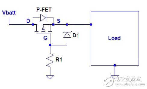
Figure 1: Battery reverse polarity protection with P-FET.
However, the use of P-channel MOSFETs requires modification of the PCB and the addition of additional circuitry.
Figure 1 shows that three components are required: a P-FET, a Zener diode, and a resistor. The P-FET needs to be sized to handle the voltage applied to the input of the module and the required load current. Also, carefully consider the thermal requirements of the system because the FET power dissipation is equal to the square of the current multiplied by the on-resistance of the FET. Zener diodes prevent MOSFET gate oxides from being damaged by overvoltage conditions. Most P-FETs can withstand voltages from 15V to 20V from the gate to source connection, so the Zener diode selection principle must be able to clamp before this voltage point. The resistor pulls the gate to ground for turning on the P-FET, but it must also be adjusted to the appropriate value. The resistance should not be too small. Too small will allow too much current to flow through the Zener diode, causing power consumption problems. However, the resistance value should not be too large, and if it is too large, the P-FET cannot be reliably turned on. In summary, the guiding idea of ​​this method is to reduce the voltage drop across the drain-to-source connection.
Power and Performance
The PACSystems* RX3i controller provides the foundation for Industrial Internet connectivity. It is a powerful, modular Programmable Automation Controller with a focus on high availability. The RX3i features a single control engine and a universal programming environment to provide application portability across multiple hardware platforms.
With integrated critical control platforms, logic, motion, HMI, process control and high availability based on GE Reflective Memory technology, RX3i increases system performance and flexibility.
Universal Development Environment Gets You Up and Running Faster:
The common software platform across all GE controllers, award-winning Proficy* Machine Edition* software provides the universal engineering development environment for programming, configuration and diagnostics for the entire PACSystems family.
- Programming tools such as tag-based programming, a library of reusable code and a test edit mode for improved online troubleshooting
- User-friendly environment that can increase design flexibility and improve engineering efficiency and productivity
Ge Plc 90-70 Cpu Parts,Cpu Parts,Io Bus Terminator Plug,Ge Fanuc Terminal Block
Xiamen The Anaswers Trade Co,.LTD , https://www.answersplc.com