
In the fiery download of the "Processor and DSP Special Issue" in December, the e-family network is missing.
FPGAs and CPUs have always been an integral part of radar signal processing. Traditionally FPGAs are used for front-end processing and CPUs are used for back-end processing. As the processing power of radar systems becomes stronger and more complex, the demand for information processing has also increased dramatically. To this end, FPGAs continue to increase processing power and throughput, and CPUs are also evolving to meet the signal processing performance requirements of next-generation radars. This trend of effort has led to an increasing use of CPU accelerators, such as graphics processing units (GPUs), to support heavier processing loads.
This article compares FPGA and GPU floating point performance and design flow. In recent years, GPUs have not only completed graphics processing, but also become a powerful floating-point processing platform, known as GP-GPU, with a high peak FLOP indicator. FPGAs have traditionally been used in fixed-point digital signal processors (DSPs), but are now enough to compete for floating-point processing and become a strong contender for back-end radar processing acceleration.
At the FPGA front end, many verifiable floating point benchmark results have been reported at 40 nm and 28 nm. Altera's next-generation high-performance FPGAs will feature Intel's 14 nm tri-gate technology with at least 5 TFLOPs. With this advanced semiconductor process, performance can achieve 100 GFLOPs/W. Moreover, Altera FPGAs now support OpenCL, an excellent programming language used by GPUs.
Peak GFLOPS indicator
Current FPGA performance can reach peaks above 1TFLOP, and AMD and Nvidia's latest GPUs are even higher, close to 4 TFLOP. However, in some applications, peak GFLOP, or TFLOP, provides limited device performance information. It only shows the theoretical floating point addition or the total number of multiplications that can be done per second. This analysis shows that in radar applications, in many cases, FPGAs outperform GPU throughput in terms of algorithms and data size.
A moderately complex and commonly used algorithm is the Fast Fourier Transform (FFT). Most radar systems often use the FFT algorithm because they do a lot of processing in the frequency domain. For example, a 4,096-point FFT is implemented using single-precision floating-point processing. It can input and output four complex samples per clock cycle. Each FFT core runs faster than 80 GFLOPs, and the resources of a large 28 nm FPGA support 7 such cores.
But as shown in Figure 1, the FPGA's FFT algorithm is close to 400 GFLOP. This result is based on "button-on" OpenCL compilation and does not require FPGA expertise. Optimized using Logical Lock and Design Space Manager (DSE), the 7-core design is close to fMAX for single-core designs, using 28 nm FPGAs to boost it to 500 GFLOPs, exceeding 10 GFLOPs/W.
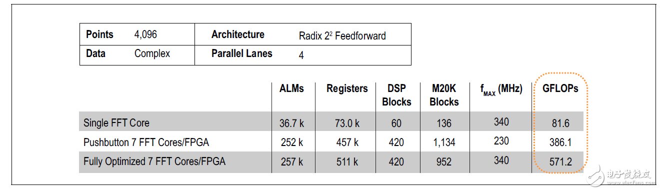
Figure 1. StraTI FFT performance of the StraTIx V 5SGSD8 FPGA
This GFLOPs/W result is much more efficient than a CPU or GPU. Compared to GPUs, GPUs are not very efficient at these FFT lengths, so no benchmarking is done. When the FFT length reaches several hundred thousand points, the GPU efficiency is relatively high, which can provide an effective acceleration function for the CPU. However, radar processing applications are typically shorter length FFTs with FFT lengths typically between 512 and 8,192.
In summary, the actual GFLOP generally only reaches a peak or a small fraction of the theoretical GFLOP. For this reason, a better approach is to use algorithms to compare performance, which can reasonably represent the characteristics of a typical application. As the complexity of the benchmarking algorithm increases, it is more representative of actual radar system performance.
Algorithm benchmark
Instead of relying on the vendor's peak GFLOP metrics to drive processing technology decisions, another approach is to use more sophisticated third-party assessments. A commonly used algorithm for space-time adaptive processing (STAP) radar is Cholesky decomposition. This algorithm is often used in linear algebra to efficiently solve multiple equations and can be used on correlation matrices.
The Cholesky algorithm is very complex in value, and a reasonable result always requires a floating point representation. The computational demand is directly proportional to N3, which is the matrix dimension, and therefore is generally highly demanding. Radar systems typically operate in real time and therefore require higher throughput. The result will typically exceed 100 GFLOP, depending on the size of the matrix and the required matrix processing throughput.
Table 1 shows the benchmark results based on the Nvidia GPU 1.35 TFLOP, using various libraries, and the Xilinx Virtex6 XC6VSX475T, which has a density of 475K LC, which is optimized for DSP processing. These devices are similar in density to Altera FPGAs when used in Cholesky benchmarks. LAPACK and MAGMA are commercial libraries, while GPU GFLOP is implemented using OpenCL developed by the University of Tennessee (2). For small-scale matrices, the latter is more optimized.
Table 1. GPU and Xilinx FPGA Cholesky benchmarks (2) 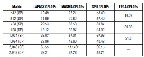
Altera tested the medium-capacity Altera StraTIx® V FPGA (460K Logic Unit (LE)) using the Cholesky algorithm for single-precision floating-point processing. As shown in Table 2, the performance of the Cholesky algorithm on the StraTIx V FPGA is much higher than the Xilinx result. Altera benchmarks also include QR decomposition, which is another matrix processing algorithm that is less complex. Altera provides Cholesky and QRD algorithms in the form of parameterizable evaluation kernels.
Table 2. Altera FPGA Cholesky and QR Benchmarks 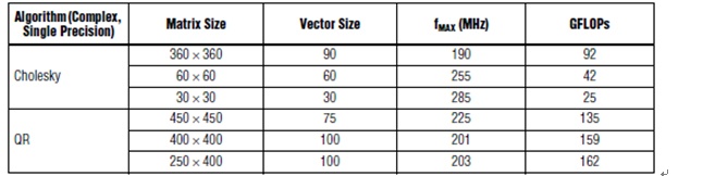
It should be noted that the matrix size of the benchmark is not the same. The results of the University of Tennessee come from the matrix of [512 & TImes; 512], while the Altera benchmark Cholesky is [360x360] and the QRD is [450x450]. The reason is that GPUs are very inefficient when the matrix size is small, so in these applications, they should not be used to speed up the CPU. In contrast, FPGAs work very efficiently on smaller matrices. Radar systems have high throughput requirements, with thousands of matrices per second, so efficiency is critical. A small matrix is ​​used, and even a large matrix is ​​required to be decomposed into small matrices for processing.
Moreover, the Altera benchmark is based on each Cholesky core. Each parameter-valued Cholesky kernel supports selection of matrix size, vector size, and number of channels. The vector size roughly determines the FPGA resources. The larger [360 × 360] matrix uses a longer vector and supports one core in the FPGA, reaching 91 GFLOP. The smaller [60 × 60] matrix uses fewer resources, so two cores can be implemented for a total of 2 × 42 = 84 GFLOP. The smallest [30 × 30] matrix supports the implementation of three cores for a total of 3 × 25 = 75 GFLOP.
FPGAs seem to be better suited to solve the problem of smaller data sizes, as is the case with many radar systems. The reason why the GPU is inefficient is because the computational load increases with N3, and the data I/O increases with N2. Finally, as the data increases, the I/O bottleneck of the GPU is no longer an issue. In addition, as the size of the matrix increases, the throughput per second of the matrix decreases drastically due to the increased throughput of each matrix. At some point, the throughput becomes so low that it does not meet the real-time requirements of the radar system.
For FFT, the computational load is increased to N log2 N, and the data I/O increases as N increases. For larger data, the GPU is an efficient computing engine. In contrast, for all sizes of data, FPGAs are efficient computational engines that are better suited for most radar applications where FFT lengths are moderate but throughput is high.
Our Fiber Optic Tools including Fiber Optic Tool Kits, Fiber Termination Tools: Fiber Splicing Tools, Fiber Network Tools, Crimp Tools, Fiber Connector Tool, Corning Fiber Tools, Fiber Stripping Tools, Cleaving Tools, Fiber Scribe Tools, Fiber Optic Mid-Access Tools, cable slitter, cable cutters, Kevlar cutters, optical connector removal tools, cable pulling tools, fiber optic work table, distance measuring wheels, heat gun and Fiber Optic Cable dispenser.
Fiber Optic Tools
Fiber Optic Tools, Fiber Cutter And Stripper, Fiber Cleaner, Fiber Susion Splicer, Fiber Optic Stripper, Fiber Splice Closure, Fiber optic Splice Boxes
NINGBO YULIANG TELECOM MUNICATIONS EQUIPMENT CO.,LTD. , https://www.yltelecom.com