
Building Door and Window Detector
Overview
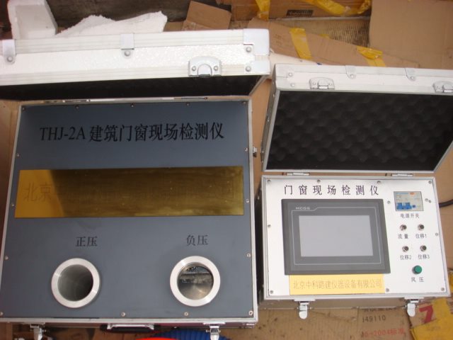
The Building Door and Window Field Detector is a new portable device developed by our company. It allows for efficient and accurate testing of air tightness, water tightness, and wind pressure resistance in building windows and doors.
It uses a manual knob to adjust air pressure, displaying the instrument's cycle detection results including air pressure, airflow, and deformation displacement. The wind source and control system are all integrated into a suitcase, making it compact, lightweight, easy to carry, reliable, and user-friendly.
Applicable Standards
JG/T 211-2007 "On-site Inspection Method for Airtight, Watertight, and Wind Pressure Resistance of Building Exterior Windows"
GB/T 7106, 7, 8 standards.
Main Specifications
Voltage: AC 220V
Power: 7.2kW
Airtight Pressure: ±200Pa
Watertight Pressure: 0 ~ +700Pa
Wind Pressure: ±2000Pa
Airflow: 20m/s (267.8 L/hour)
Working Environment
1. Relative humidity: ≤85% without condensation;
2. Temperature: 0 ~ 50°C;
3. Altitude: <1500 meters;
Display the correspondence between channel number and detected value
Channel Number | Measured Value
CH1 | ±200Pa pressure
CH2 | Airflow 0 ~ 267.8 L/hour (20m/s)
CH3 | ±6000Pa pressure (Actual = Display ×10)
CH4, 5, 6 | Three-point displacement display, 0 ~ 20mm
Steps
1) Install the static pressure box, air path, and water system;
2) Open the suitcase and insert the straight pipe section of the wind pipe into the positive pressure port;
3) Insert the airflow meter into the straight pipe and connect its cable plug to the socket on the suitcase;
4) Apply plastic cloth to the window and insert the hose into the plastic bag, sealing it with tape;
5) Insert the pressure tube into the controller and clamp it inside the plastic bag;
6) Close the air switch, turn on the power, and ensure the airtight indicator is on;
7) Adjust the “Voltage†knob counterclockwise to the minimum;
8) Press the “Airtight†and “Wind 1†buttons; if wind is insufficient, press “Wind 2†as well;
9) Rotate the “Voltage†knob clockwise while monitoring the CH1 pressure value to reach 150Pa;
10) Press “Wind Power 1†button;
11) When the pressure returns to zero, press “Wind Again 1†to stabilize at 150Pa for 3 seconds, then press “Wind Power 1†again;
12) Repeat steps 9–11 and adjust the “Voltage†knob to the minimum;
13) Press “Wind Power 1†button;
14) Slowly rotate the “Voltage†knob clockwise while watching the CH1 pressure stabilize at 100Pa for 10 seconds;
15) Continue rotating the knob clockwise until the pressure reaches 150Pa and stabilizes for 10 seconds;
16) Rotate the “Voltage†knob counterclockwise until the pressure returns to 100Pa and stabilizes for 10 seconds;
17) Adjust the “Voltage†knob to the minimum;
18) Insert the straight pipe section into the negative pressure port;
19) Slowly rotate the “Voltage†knob clockwise while watching the CH1 pressure reach -150Pa;
20) Press “Wind Power 1†button;
21) When the pressure returns to zero, press “Wind Again 1†to stabilize at -150Pa for 3 seconds, then press “Wind Power 1†again;
22) Repeat step 19 once and adjust the “Voltage†knob to the minimum;
23) Press “Wind Power 1†button;
24) Slowly rotate the “Voltage†knob clockwise until the pressure stabilizes at -100Pa for 10 seconds;
25) Continue rotating the knob to reach -150Pa and stabilize for 10 seconds;
26) Rotate the “Voltage†knob counterclockwise until the pressure stabilizes at -100Pa for 10 seconds;
27) Adjust the “Voltage†knob to the minimum;
28) Insert the straight pipe section into the positive pressure port;
29) Press “Wind Power 1†button;
30) Slowly rotate the “Voltage†knob to reach 500Pa and stabilize for 3 seconds, then press “Wind Again 1â€;
31) Repeat steps 28–30 and press “Wind Power 1â€;
32) Open the sprinkler system to regulate the water flow to 2L/min/m² and start spraying;
33) After 5 minutes of spraying, press “Wind Again 1†and slowly rotate the “Voltage†knob to stabilize at 100Pa for 5 minutes;
34) Continue increasing pressure step by step to 700Pa and stabilize for 5 minutes to complete the stable pressure test;
35) Spray for another 5 minutes, press “Wind Again 1â€, rotate the knob to stabilize at the design pressure for 15 minutes to complete the design value test;
36) Adjust the “Voltage†knob to the minimum and press “Wind 1†button;
37) Prepare for pressurization;
38) Insert the straight pipe into the positive pressure port;
39) Rotate the “Voltage†knob to reach 500Pa and press “Wind Power 1â€;
40) When the pressure returns to zero, press “Wind Again 1†to stabilize at 500Pa for 3 seconds, then press “Wind Power 1†again;
41) Repeat step 40 and adjust the “Voltage†knob to the minimum;
42) Press “Wind Power 1†button;
43) Rotate the “Voltage†knob to reach 200Pa and record the displacement values from CH4, 5, 6 to calculate deflection B ≥ 1/300;
44) Rotate the knob to 400Pa and record the same data to check B ≥ 1/300;
45) Continue rotating to 1800Pa and record the data to ensure B ≥ 1/300;
46) Rotate to 2000Pa and record the data to confirm B ≥ 1/300;
47) Adjust the “Voltage†knob to the minimum;
48) Insert the straight pipe into the negative pressure port;
49) Rotate the “Voltage†knob to reach -500Pa and press “Wind Power 1â€;
50) When the pressure returns to zero, press “Airtight†to stabilize at -500Pa for 3 seconds, then press “Airtight†again;
51) Repeat step 50 once and adjust the “Voltage†knob to the minimum;
52) Press “Wind Power 1†button;
53) Rotate the “Voltage†knob to reach -200Pa and record the displacement values to calculate B ≥ -1/300;
54) Rotate to -400Pa and record the same data to ensure B ≥ -1/300;
55) Continue to -1800Pa and record the data to confirm B ≥ -1/300;
56) Rotate to -2000Pa and record the data to check B ≥ -1/300;
57) Adjust the “Voltage†knob to the minimum;
58) Turn off the air switch and power, ensuring the indicator light is off;
59) End the test;
60) Adjust the “Voltage†knob to the minimum;
61) Press “Wind 1†and “Wind 2†buttons;
62) Turn off the air switch and power, and ensure the power indicator is off.
Precautions
1) Ensure the airflow meter is inserted correctly into the straight pipe;
2) Connect a reliable grounding wire at the site for safety;
3) Convert all units to match the standard requirements for accurate judgment.
I-type Inductance Core,I Inductor Model,Ring I-type Inductance,Design Of I-Shaped Inductor
Xuzhou Jiuli Electronics Co., Ltd , https://www.xzjiulielectronic.com