
Using AT89C205l single-chip computer chip to design and manufacture a "smart detection control circuit" for the water heater, it can monitor the water level of the water tank and the working state of each group of electric heating tubes in real time. Once the water level of the water tank is abnormal or the electric heating tube is faulty, it can be automatically Complete the protection action and give the corresponding sound and light alarm signals, prompting the maintenance management personnel to carry out maintenance in time. The circuit has the advantages of simple structure, easy manufacture, convenient use and the like.
1. Main functions and features(1) The circuit is simple, all circuits use a "single chip" chip and two auxiliary chips, with a small number of peripheral discrete components, the relevant control functions can be completed.
(2) When the initial power is applied, the system will detect the water level of the water tank. Only when the water level of the water tank is normal (the water level switch SVV is closed), the three-phase solid state relay SSR will be turned on, and the electric heating tube will be energized. After that, the system will periodically monitor the water level of the water tank. Once the water level of the water tank is lower than the preset minimum water level {that is, the automatic water supply pipeline system is faulty), when the SVV switch is disconnected, the system will immediately cut off the power supply of the electric heating tube and give “water shortageâ€. "Sound and light alarm signals."
(3) When the electric heating pipe is energized, the system will monitor the working status of the three sets of electric heating pipes connected to the three-phase electric power and give the corresponding luminous tube indication on the control panel. When each group of electric heating tubes is working normally, the three sets of electric heating tube working status indicators on the panel will be illuminated at the same time. If a group of electric heating tubes is damaged, the corresponding group of electric heating tube indicators on the panel will start to “blinkâ€, indicating that the group of electric heating tubes is faulty, indicating that it needs to be repaired and replaced, but the water heater can still work barely, but the water is The time to boil should be extended accordingly. If some two or three sets of electric heating tubes are damaged at the same time, the three sets of electric heating tube indicators on the panel will be “flashing†at the same time, and the buzzer will also emit an alarm sound of 嘀, 嘀, 嘀, indicating the electric heating of the water heater at this time. The tube is no longer working properly and must be repaired and replaced immediately.
(4) When the temperature switch WK is in the ON state, it indicates that the water in the water tank has not been boiled. When the water level of the water tank is normal, the system will control the SSR of the three-phase solid state relay to be turned on, so that the electric heating tubes of each group are energized.
At the same time, the “heating†indicator on the panel will be illuminated. When the WK is disconnected, it indicates that the water in the water tank has been boiled. At this time, the “heating†indicator on the panel is white-extinguished, the “insulation†indicator will be illuminated, and each group of electric heating tubes will be powered on.
(5) The input and output of this circuit are all optically isolated, with strong anti-interference ability and stable and reliable operation.
2, the circuit principleThe circuit is shown below.
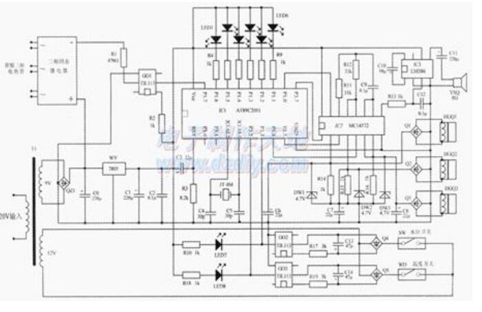
AT89C2O5l "single chip" chip IC1 is the core of this circuit, C3 and R3 constitute a simple power-on automatic reset circuit. The related pins of JT, C1, C2 and IC1 form the clock circuit of the "single chip microcomputer". Only 13 of the 15 I/O ports of IC1 are used. Among them, P1.1-P1.6 is used as the output control port of each indicator of the control panel, and is connected to an LED light-emitting diode through a current limiting resistor. On the negative pole, the low level is effective and directly drives the LED display. P1.7 is the load (electric heating tube) control port. It is connected to the 2 pin of the photocoupler GO1 through a current limiting resistor. Its 1 pin is connected to +5V. When P1.7 is high, GO1 and three-phase solid state. The relays are all turned off, and the electric heating pipes are not energized. When P1.7 is low, GO1 and the three-phase solid state relay are turned on, and each electric heating tube is energized. P1.0 is the alarm signal control output port, which is connected to pin 15 of IC2. IC4's 10-14 pin and outer ring components are connected into a controllable audio oscillator. Its 15 pin is the control terminal (high-level active 1, 9 pin is the output terminal, and the output signal is composed of IC3. After amplification, the speaker is driven. When the P1,0 of the single-chip microcomputer is output to low level under software control, the controllable audio oscillator is in the state of vibration stop, so there is no sound in the speaker. When the circuit needs to send an audio alarm signal, pass the software. Control, so that the P1.0 of the single-chip microcomputer intermittently outputs a high-level signal, then the controllable audio oscillator will work intermittently, causing the speaker to emit an alarm sound of 嘀, 嘀, rm. The 1-7 feet of IC2 constitute electric heating. The tube working state monitors the signal level conversion circuit.
The electric heating tube working state Sensor adopts the TAl420 type, which is a vertical type, core-through (5), and can be directly mounted on the printed circuit board. The small precision AC current transformer (HGQ1~HGQ3) has a fully enclosed, mechanical It has good environmental resistance, strong voltage isolation, beautiful appearance, high precision, wide sampling range and flexible application. In use, one power lead of each group of electric heating tubes is passed through the core hole of the corresponding current transformer of the group, so that when each electric heating tube works normally, the electric heat passing through each current transformer The AC current will pass through the pipe power connection. Due to the mutual inductance, a mutual inductance AC signal will be generated at the coil end of each current transformer. The signal is converted to a high level by the three sets of Q1-Q3 rectifier bridges. The DC signal voltage is connected to the 2, 4, 6 (7) pins of IC2, and the high level is converted to the low level by IC2, and then output from the 1, 3, and 5 pins respectively, and connected to the P3.4 and P3 of the single chip microcomputer. .5, P3.70 Obviously, if a certain group of electric heating tubes does not work, the corresponding current transformer will not have an induction signal output, and IC2 and its corresponding output end will not have a low level signal output, so In conjunction with the software, the working state of each electric heating tube can be accurately identified and corresponding indications can be given by corresponding LEDs.
The DWI~DW3 Zener diode is mainly used to protect the output signal of the current transformer from the VCC operating voltage (+5V) of IC2 and damage the relevant input of IC2. The water level signal sensor adopts a normally-on (water level normally on) type float type liquid level switch, which is connected in series to the input control loop of GO2, and the output end of GO2 is connected to the "inverter" circuit, from 5 feet. The output is connected to P3 of the microcontroller. By cooperating with the software, the water level state can be accurately identified and the illuminating signal of the "water shortage" alarm is given by the corresponding LED. As mentioned above, the sound signal of the water shortage alarm is a high level signal that the software controls the P1.0 output to interrupt, and controls the audio oscillator to work intermittently, so that the speaker emits an alarm sound of hum, hum, and hum. The temperature signal sensor adopts a temperature control switch WK with a temperature value of 980C, which is connected to the input control loop of GO3, and the output end of GO3 is also connected with "inverted phase". The circuit is output from pin 5 and connected to P3.2 of the single-chip microcomputer. By cooperating with the software, the water temperature state can be accurately identified and the electric heating tube can be controlled by the output control terminal, and the corresponding LED is passed. Give a status indication of "heating" or "insulation". Power transformer T1, bridge rectifier QZ, 7805 three-terminal regulator WY and C1, C2 constitute a power supply circuit, which can provide stable +5V DC working power for the whole circuit.
Multi function remote manual pulse generator for control of all axes.
Manual Sensor,Miniature Optical Kit Encoder,Rotary Encoder With Led Ring,Optical Quadrature Encoder
Yuheng Optics Co., Ltd.(Changchun) , https://www.yuhengcoder.com