
Description of the program:
Basic functionThe bus emulation and test system can receive, monitor, record, and play back all ARINC429, MIL-STD-1553, AFDX bus signals, discrete signals, analog signals, etc. of the computer channel, through various data signals through intuitive data monitoring. With the analysis function from the original code to the physical meaning, it can quickly and effectively perform system test, operation record, fault location and status monitoring.
The block diagram is as follows:
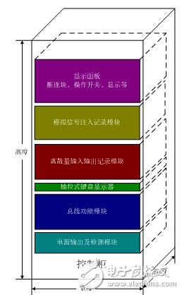
The integrated avionics simulation and test system simulates and tests ARINC429, 1533B and AFDX bus signals including: data transmission, protocol verification, electrical performance, noise suppression, error injection, transmission status, etc. Testing, analysis and fault diagnosis And provide a good graphical interface to complete the above simulation and testing functions.
The provided analog output channel has a voltage range of ±10V per channel, and realizes signal test, signal display, signal recording, signal analysis, recording (automatic report generation), and signal playback of analog signals. Two analog signal injection methods are provided: automatic injection (test equipment injection) and manual injection (1~2 external standard source injection). The selection of the injection mode is selected by the front panel disconnect block and provides signal indication.
Channels for discrete outputs and channels for discrete inputs. Among them, the discrete output channel is controlled by the front panel switch, and the discrete input channel is realized by the disconnecting block and the signal light. It also provides functions such as discrete recording, display, and automatic report generation.
Provides detection of secondary power (-5VDC, ±15VDC) inside the computer under test, real-time display, recording and other functions.
2. System solution implementationThe simulation test process of most systems can be divided into the mathematical model simulation test phase, the semi-physical simulation test phase of a single device, the semi-physical joint simulation test phase of multiple devices, and the physical simulation test phase. At present, most of the simulation test equipment on the market can only meet the requirements of single-stage simulation test, and the inheritance and scalability of the hardware system are poor, resulting in a large number of hardware duplication construction. And the simulation test equipment at different stages has a great difference in software usage habits, which brings a lot of unnecessary labor to the system simulation designer and the inspection personnel.
Therefore, we hope to provide a versatile and scalable simulation and detection system solution that meets the needs of customers for simulation and testing at different stages of development, reducing the familiarity of software usage and improving work efficiency. Save on hardware costs.
2.1 Mathematical model simulation phase
System composition:
Hardware: PC + Reflective Memory Network
Software: Windows/RTX + Matlab/Simulink + Labview
The avionics bus simulation system hardware platform is divided into two parts: the host system (master computer) and the target system (cockpit display control system, high lift control system, flight control computer, radar, etc.). The host system and the target system are connected by a reflective memory network and Ethernet. The reflective memory network is used to transmit simulation parameters and simulation results in real time; Ethernet is used to transmit other file information and interactive content.
2.2 Semi-physical phase: single device
System composition:
Hardware: PC + Reflective Memory Network + Bus Simulation and Detection Equipment
Software: Windows/RTX + Matlab/Simulink + Labview + Vxworks
In the semi-physical stage, the simulation system of this stage can be built with the reflection memory network and the avionics bus simulation and detection equipment. The host completes the establishment and modification of the simulation model, and the avionics bus simulation and detection equipment completes the operation of the simulation model and the ICD and DDR file control of the data interaction with the avionics bus. The dynamic simulation of avionics equipment is realized on the avionics bus simulation and detection equipment to meet the requirements of the ground dynamic simulation test of the aircraft avionics system.
2.3 Semi-physical phase: multiple devices
System composition:
Hardware: PC + reflective memory network + multiple bus simulation and detection equipment
Software: Windows/RTX + Matlab/Simulink + Labview + Vxworks
The host system uses MATLAB and Simulink to create system models, analyze models and preliminary tests, convert the models into C code and compile them through customized templates and scripts, automatic code generation tools, and distribute executable files to the target system through a reflective memory real-time network. Run in real time. At the same time, through the I/O module library under Simulink, the modules in each target system are connected to the external system through the I/O board. The reflective memory network can realize real-time data transmission between each target system. Therefore, the target machine can realize real-time operation of the model, online parameter setting, data acquisition, and event monitoring. The whole system is characterized by the designer can work completely at the Simulink level, and the built model can be run in real time in the hardware loop without writing code.
In summary, the integrated avionics bus simulation and test system is mainly used in the semi-physical simulation test phase, which not only meets the functional requirements of real-time simulation and detection, but also has the advantages of flexible application and easy expansion.
3. Program evaluationThe above solution can not only meet the customer's demand for avionics bus, analog digital signal, power detection, but also easy to expand, build a simulation system, complete the PFC cross-linked avionics environment, high lift control system, automatic flight control system and other models. Simulation to meet the needs of users for simulation testing at different stages of development.
3.1 Intelligent
The bus function module uses the widely proven GE avionics adapter card to perform bus simulation and test tasks reliably and efficiently. At the same time, the software provides one-button operation, which can intelligently complete the testing and recording of all aspects of ARINC429, 1553B and AFDX bus, analyze the automatic test data, monitor the status of the tested system, and have error warning function; Fault location can occur when it occurs.
3.2 Modularity
The bus function module and the analog and digital signal simulation detection modules are separated and controlled by two main control boards, which is beneficial to reducing the load of each main control board and improving the stability of the main control board during operation. The modularity of the software design makes it easy to modify or add system functions to easily meet customer needs changes and feature upgrades. The open data monitoring API makes it easy for users to expand the number of monitoring terminals. The target machine simulation interface library enables the user to carry out secondary development and customize the master program that is completely suitable for oneself.
3.3 Networking
The system provides a remote control interface via Ethernet. Setting up a Webserver in VxWorks allows you to access the test system via Ethernet. It can send, start, pause, or stop test control commands. It can also extend the monitoring terminal through Ethernet or real-time network to solve geographical restrictions. At the same time, users can easily download and manage simulation and test data.
3.4 Real-time
The VMIC5565 series, which reflects the memory card, has a transfer speed of 174 Mbytes/sec. With fiber optics, more nodes can be connected (up to 256 nodes) with high immunity to interference. The test results show that from the data written to the RAM to the reflective memory card transmitted to another node, there is less than 400 nanoseconds delay, which can ensure the real-time performance of the system. At the same time, the user can use the reflective memory network to easily build a simulation test platform in different development stages, which is easy to expand.
Laser Engraving Logo Wood Usb Flash Drive Memoria Usb 4GB 8GB 2.0 3.0
1. Make the logo on usb as the customers design
2. Can preload the file intousb and make the file non-delete
3. The advertisement file can be Auto-play when plug usb into the computer
4. Add more value to your giveaway by adding a Key Chain,Lanyard Neck String or USB Extension Cable
5. Ask us about a wide selection of packaging options,including variety of gift boxes and customized clam shells
6. Making encryption to protect your data
Wooden Usb Flash Disk,Biodegradable Card Usb Flash Dis,Environment-Friendly Card Usb Flash Disk,Flash Disk
MICROBITS TECHNOLOGY LIMITED , https://www.hkmicrobits.com