
As we all know, stepper motors are mainly classified according to the number of phases. Usually we have four phases, two phases, three phases, and so on. Therefore, the small series mainly introduces the difference between the three-phase stepper motor and the two-phase stepper motor. Firstly, the difference between them is introduced. Secondly, the three-phase stepper motor and two-phase stepper motor step angle are described. The gap between the specific follow Xiaobian to learn more about it.
The difference between three-phase stepper motor and two-phase stepper motor1, the number of phases of the motor
It means that the number of coils inside the motor is different. The inside of the two-phase stepping motor is composed of two coils. The inside of the three-phase stepping motor is composed of three coils.
2, the step angle of the motor
Refers to the angle of each step taken by the motor. Generally, the step angle of the two-phase motor on the market is 0.9°/1.8° and the three-phase motor is 0.75°/1.5°.
3, the size of the motor
The three-phase motor is generally a large motor, so the size is generally larger than the two-phase motor, which also determines that the three-phase stepper motor is smoother than the two phases.
4, torque
Two-phase motors have the same torque as the three-phase torque.
5, accuracy
The subdivision function of the two-phase stepper motor driver is more and more powerful, and the two phases can also achieve the accuracy that can be achieved by three phases.
The high-speed performance of the three-phase stepping motor is good (characteristic is hard), and the step angle of the two-phase stepping motor is smaller and the accuracy is better. Since the torque decreases slowly with increasing speed, it is often used in applications where high accuracy is required.
1, determine the step angle factor
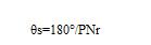
The higher the stepper motor resolution (the number of steps in one turn, 360° divided by the step angle), the higher the positional accuracy. In order to obtain high resolution, more poles are designed. The PM type rotor is arranged such that the N and S poles are alternately arranged on the outer surface of the iron core of the rotor, and the number of rotor poles is the sum of the number of N poles and S poles. For simplifying the explanation, it is assumed that the number of pole pairs is 1. The step angle θs of the stepping motor in which the rotor is a permanent magnet is represented by the following equation, where Nr is the number of rotor pole pairs and P is the number of stator phases. (The HB type stepping motor Nr described later in this lesson is the number of rotor teeth. ):
The physical meaning of the above formula is as follows:
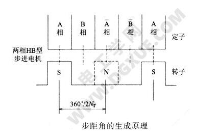
The mechanical angle of rotation of the rotor is 360 degrees. For example, if the number of poles is 2Nr, it is equivalent to a mechanical angle of 180°/Nr. This means that a pole mechanical angle is divided by the number of stator phases to obtain the step angle. This concept is shown in the figure below.
From the formula θs=180°/PNr, the smaller the step angle, the higher the resolution. Therefore, to increase the resolution of the stepping motor, it is necessary to increase the number of rotor pole pairs or use a polyphase with a higher number of stator phases P. method. The increase in Nr is limited by machining, so it takes two methods to produce high-resolution stepper motors.
2, two-phase stepper motor
The simplest configuration of the two-phase stepper motor is Nr=1. The structure of the motor is shown in the figure below. In general, the number of stator poles of a two-phase motor is a multiple of 4, at least 4. The rotor is a two-pole rotor with one N pole and one S pole.
The stator is usually made by laminating silicon steel sheets. The number of stator poles is 4 poles, which is equivalent to one phase winding occupies two poles. Phase A poles are 180° apart in space and phase B poles are also 180° apart in space. Current flows positively and negatively within a phase winding (this driving method is called bipolar driving). The phase difference between phase A and phase B is 90°, and the rectangular wave current flows through the two phases alternately.
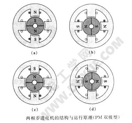
That is, the stator of a two-phase motor has a spatial phase difference of 90° when Nr=1, and the current is 90° out of phase with respect to time. The current is similar to an ordinary synchronous motor. A rotating magnetic field is generated on the stator, and the rotor is attracted by the rotating magnetic field. The magnetic field rotates synchronously.
The figure above shows the structure of the two-phase stepper motor (PM type) and its operating principle. Rotate 90° clockwise from Figure (a) to Figure (b). Rotate 90° in sequence (c) and (d). Continuous operation becomes continuous rotation.
For example, if the A-phase has two coils, and the unidirectional currents alternately flow through the two coils, the opposite magnetic flux direction may also be generated. This is called a uni-plar coil.
As shown in the figure below, only a single direction of current flows through the coil. This coil is called a unipolar coil. The other type of coil is a bipolar coil in which current flows in the forward and reverse directions. The advantages and disadvantages of the two coils are as follows. Will be introduced in detail later in the course. The unipolar coil can replace the bipolar coil shown in the figure above, with the same step angle during operation.
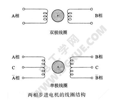
The two-phase unipolar coil in the above figure is also referred to as a four-phase stepping motor in some literatures. At this time, the number of rotor pole pairs, the number of teeth Nr, and the step angle θs are the same as those of the bipolar coil. The definition of the two-phase motor in this course is in accordance with the formula θs=180°/PNr, that is, the number of teeth of the rotor and the step angle θs are substituted into the equation θs=180°/PNr. If P=2, it is a two-phase motor. If Nr is the same, P= 4, step angle θs is only 1/2, then the motor is a four-phase motor, which draws special attention.
Two-phase stepping motor is widely used nowadays. The structure of actual motor is more complex than the diagram (the structure and operation principle of PM bipolar two-phase stepping motor). In addition to lamination, the stator has claw pole structure, but the basic principle can be referred to. Figure (PM bipolar two-phase stepper motor structure and operating principle), the rotor shown in the figure is called PM type (permanent magnet or permanent magnet) rotor, the outer surface of the magnetic cylinder forms the rotor pole.
3, three-phase stepper motor
The stepper motor (VR type or reactive or variable reluctance type) with no permanent magnet rotor has long been used in three-phase stepper motors. In 1986, Japan's servo company developed a stepper motor with permanent magnets and stator poles with teeth (the design principle of magnetic pole teeth will be described in detail later). The matching of stator and rotor pitches can achieve higher angular resolution. And torque. The number of main poles of the three-phase stepper motor stator coil is a multiple of three, so the number of stator main poles of the three-phase stepping motor is 3, 6, 9, 12 and so on.
The stepper motor (VR type or reactive or variable reluctance type) with no permanent magnet rotor has long been used in three-phase stepper motors. In 1986, Japan's servo company developed a stepper motor with permanent magnets and stator poles with teeth (the design principle of magnetic pole teeth will be described in detail later). The matching of stator and rotor pitches can achieve higher angular resolution. And torque. The number of main poles of the three-phase stepper motor stator coil is a multiple of three, so the number of stator main poles of the three-phase stepping motor is 3, 6, 9, 12 and so on.
The following figure shows the comparison of the typical stator structure and drive circuit for stepper motors with different phases. The rotor structure diagram is omitted. It is assumed that the rotors are all of PM type or HB type, and the corresponding rotors are provided on the basis that the stator is two-phase, three-phase, and five-phase. The stator adopts the structure of the minimum number of main poles that does not generate unbalanced electromagnetic forces (will be introduced in detail later, the rotors are not attractive and can not fully cancel each other out to generate residual radial forces), that is, two phases are four main poles, three When the three main poles are phases and the five main poles are five phases, an unbalanced electromagnetic force will be generated in the structure, and the above structure will not be used except for special purposes. In the figure, the stator is composed of eight main poles for two phases, six main poles for three phases, and ten main poles for five phases, which is the simplest structure.
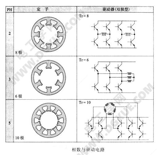
On the other hand, if a stepper motor drive circuit is used for a bipolar coil, the number of power tubes is 8 for the two phases and 10 for the five phases. The three phases are connected by Y or â–³ The relationship between the methods, the three outlets drive only 6 power tube is enough, so from the motor and the driver as a whole, the structure of the three-phase stepper motor is the simplest, and the two of the lowest manufacturing costs.
From the standpoint of the number of odd and even number of stator phases, the number of switching power transistors in the driving circuit in the odd-numbered case is smaller than that in the even-numbered case, for example, the number of driving power transistors of the three-phase stepping motor is smaller than that of the two-phase stepping motor. The three-phase driver ICs are now available for sale at companies such as Sanken Electric, Sanyo Electric, and New Eramoto Industries. Compared with the two-phase stepping motor, the three-phase stepping motor has the advantages of 1.5 times resolution and low vibration at the same number of rotor teeth. Therefore, the number of use will increase and the price will decrease. It is hoped that it can become a serialization. Stepper motors, whose performance will be described in detail later.
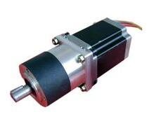
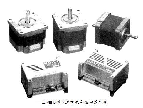
For the three-phase permanent-magnet stepper motors, there are no documents previously introduced in the system other than this course. This course will introduce the three-phase HB stepper motors (42mm and 60mm) in detail. The outline of the driver is shown in the figure below.
APM DC source system is programmable DC Power Supply which can output high power. Users can set the output voltage,current arbitrarily .Measure all kinds of features and display on VFD. As for this DC source system,output voltage is up to 1200VDC max (recommend not to exceed 800V) by connecting the internal single unit in series.
High voltage dc power supply output current is up to 2000A max by connecting the internal single unit in parallel. Maximum power and height of the adjustable power supply is in 10.8kW, 21.6kW, 36kW and 6U, 12U ,20U high respectively.
Some features as below:
- With accurate voltage and current measurement capability.
- Coded Knob, multifunctional keyboard.
- Standard RS232/RS485/USB/LAN communication interfaces, GPIB is optional.
- Remote sensing line voltage drop compensation.
- Equips with LIST waveform editing function.
- Use the Standard Commands for Programmable Instrumentation(SCPI) communication protocol.
- Have obtained CE certification.
DC Source System,30V Power Supply,Digital DC Power Supply,Dc Constant Power Source
APM Technologies Ltd , https://www.apmpowersupply.com