
Officials who have used oscilloscopes will find that oscilloscopes with bandwidths greater than 200M will have two input impedances to choose from. One is the common 1MΩ, and the other is the main character of this paper is 50Ω. What is the use of this 50Ω, the input impedance should not be higher, the better. Next we will come together to understand this mysterious 50Ω.
Transmission line
Just like history, I have to insert a military theory class. If I want to explain our 50Ω, I have to talk about this transmission line. It is well known that electrical signals are actually propagated in the transmission line in the form of electromagnetic waves. When the size of the transmission line is no longer much smaller than the wavelength of the electromagnetic wave, the characteristics of this "wave" have to be considered.
Light is reflected when the transmission medium changes, and the electrical signal is the same. What does reflection bring, and your signal may be like this.
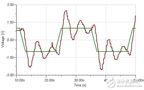
figure 1
Isn't the whole person not very good? In order to prevent reflections from occurring, uniform transmission lines, such as PCB microstrip lines, coaxial lines, etc., have uniform media, and the cross-section geometry is the same at any point, so that electrical signals are not reflected in the transmission line. But the problem is coming again. Sending a thousand miles, the end must be a different, the transmission line should still give the signal to the load of the signal sooner or later. Once the signal comes to the end of the transmission line, is it still necessary to reflect? Fortunately, our electrical signals are not as emotional as light. As long as her instantaneous impedance is guaranteed, she can also not reflect back. Instantaneous impedance is the impedance of an electrical signal at a certain point on the transmission line. It has been found through research that the instantaneous impedance of a uniform transmission line is purely resistive, independent of frequency, like a resistor, and the instantaneous impedance is only related to the geometry and filling of the transmission line. Related to materials, so it is called characteristic impedance. Since the instantaneous impedance is like a resistor, then we will connect a resistor in parallel with the load so that the total resistance and the characteristic impedance are equal, so that the signal will not have much disgust, and will be conquered and transferred to the load without being reflected back. Your circuit will be clean. This method is called terminal matching. Another method is source-side matching, that is, a resistor is serially connected to the source to add the output resistance of the signal source equal to the characteristic impedance of the transmission line, so that the load of the reflected wave is equal to the impedance of the transmission line, thereby absorbing the reflection. Wave, don't let it hit and hit on the transmission line. Many times these two matches are used simultaneously.
Famous 50Ω
The characteristic impedance affects the electrical properties such as signal transmission power, transmission loss, crosstalk, etc., and its board and geometry affect the manufacturing cost. In this case, only a compromise can be found. And 50Ω is an optimal balance point for transmission power, transmission loss, and manufacturing cost of coaxial lines. Therefore, most high-speed signals use a 50Ω characteristic impedance system, which forms the standard and is still used today, becoming the most widely used impedance standard. For example, the common PCIE has a single-ended impedance of 50Ω.
This is the origin of this 50Ω, but has not explained why there is a 50Ω on the oscilloscope to prevent signal reflection, yes, this is really a reason, but in addition to this, he has other meanings.
Oscilloscope load effect
I believe that everyone has this experience, debugging a problematic circuit, want to look at the waveform, the result is normal after the probe circuit is connected, and the probe circuit is removed again. This is caused by the load effect. The equivalent model of the oscilloscope in 1MΩ impedance mode is more complicated, and can be roughly equivalent to a form in which 1MΩ and a capacitor of a dozen pF are connected in parallel.
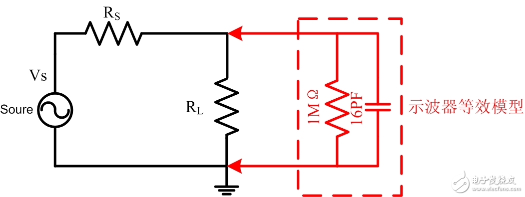
figure 2
This 1MΩ is the specification for an oscilloscope. Capacitance is a parasitic parameter that we don't want but that is inevitable. At DC and lower frequencies, 1MΩ dominates. When the frequency exceeds 10M, the capacitor will become the main load. Due to the introduction of these two parameters, the signal at the time of measurement is different from the original signal, which causes an error in the measurement result. So how big is the difference, it also depends on the output resistance and load of your circuit under test. Just follow the example above. According to the Thevenin theorem, it can be changed to:
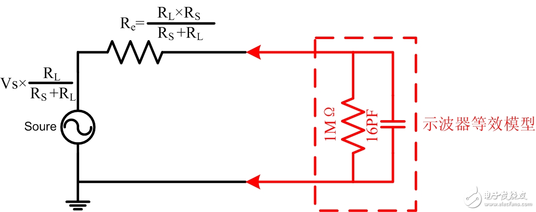
image 3
It can be seen that the original signal is; ; the difference of the low frequency signal is mainly determined by the partial pressure of the Thevenin output resistance Re and 1MΩ, and at the high frequency, the partial pressure of Re and 16pF capacitive reactance is required.
According to the calculation, if the value of Re is 10Ω and the frequency of the signal is 200M, the load effect of the oscilloscope will cause a deviation of about -0.2db. And if your system's Re is 25Ω, then this deviation will reach -1db. If it is 50Ω, 100Ω, no doubt the error will be bigger and bigger.
In order to make the measurement more accurate, the oscilloscope must compensate some of these deviations by adding some compensation measures internally (of course, this compensation is only relative to the measurement result and the original signal, and the internal compensation cannot reduce the measurement signal and the original signal. difference between). That specific should be compensated according to that situation. As we already know, the 50Ω system is the most widely used in high-speed signals, so we choose 50Ω system that is Re=25Ω to compensate. The oscilloscope manufacturer will compensate for the best signal in this case. So if you are a 50Ω system, the oscilloscope measures the closest effect to the original signal. If your equivalent output resistance is much different from 25Ω and the frequency you need to measure is high, you need to evaluate if the measurement error is within your allowable range. It is recommended to use a 10:1 probe for measurement because its parasitic capacitance is lower than that of an oscilloscope, while the load capacitance of a 1:1 probe is basically around 50pF, and its load effect is much more serious than the oscilloscope itself. If the 10:1 probe still does not meet your needs, measure the active probe with a smaller parasitic capacitance.
Imagine if you use an oscilloscope to connect directly to a high-frequency signal generator to measure the high-frequency signal output by the signal generator, and the output resistance of the high-frequency signal generator is 50Ω. What happens? As can be seen from the above, the load will seriously affect the measurement results. Combined with the transmission line theory, it can be seen that there will be a reflected wave reflected back to the signal source, which can be fatal for some sophisticated instruments. So this time you need to add a 50Ω termination adapter or use the internal 50Ω gear. This greatly reduces the reflection of the signal and minimizes the measured signal being affected by the load effect. This is what the oscilloscope's 50Ω impedance does.
Oscilloscope measurement considerations related to 50Ω
Combine the theory of transmission line and the load effect of the oscilloscope, and pay attention to the points related to 50Ω in oscilloscope measurement. Of course, you don't need to consider these when measuring lower frequency signals.
1. When the oscilloscope uses 50Ω termination or internal 50Ω gear, only 50Ω coaxial cable or some active probes that require 50Ω matching can be used. Active sensors can only be used when measuring on-board signals directly, and coaxial cables are only suitable for measuring no-load signals (such as signal generators).
2. When measuring high frequency signals, pay attention to the load effect of the oscilloscope. The measurement system is preferably a 50 Ω system. Considering the transmission line theory, it is best to use the probe to directly measure the load side instead of the middle PCB.
3. When measuring the output waveform of the signal generator, a 50Ω termination is required. Otherwise, the measurement results will be seriously affected by the oscilloscope load effect.
Extracurricular articles
Yang Minggong, a brother of the Ming Dynasty, taught us to say: "When you are aware of the sensation of the line, you know that it is true that you know what you are doing." True knowledge is obtained in the process of constant unity of knowing and doing. In the process, you will need some partners who can help you discover the truth. And the new ZDS2024 Plus from Guangzhou Zhiyuan will be a good choice for you. It supports oversized storage of 250M points and can see much more detail than other oscilloscopes at larger time bases. Support more than 20 kinds of protocol triggering and decoding, and have a variety of computing functions such as FFT, which will make your 'row' and "know" more quickly 'integrated'.
110Kv Oil-Immersed On-Load Transformer
Siemens Gis Switchgear,Switchgear For Home,Megawin Switchgear Turnover,Eaton Magnum Ds Switchgear
Shandong Shunkai electrical equipment co., LTD. , https://www.chinasdsk.com