
To cope with the noise interference of electronic equipment, it is necessary to know not only the noise source, but also the characteristics of the transmission path and the antenna. This section details the transmission paths.
Prior to this, the generation of noise (except harmonics) has been explained by a relatively simple expression. However, when interpreting the mechanism of noise transmission and transmission, the terms used in transmission theory, electromagnetics, and antenna theory are mentioned (as shown in Figure 3-1-1). If you don't understand these terms, you can't handle the noise problem.
Therefore, this section will explain these terms (using as few formulas as possible) and introduce important topics on noise such as resonance and damping, noise conduction and reflection, and source impedance.
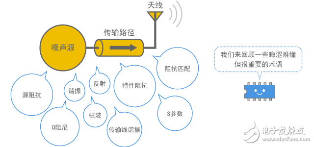
Figure 1 What will be introduced in this chapter
Resonance and damping
Resonance is an important factor in producing noise or receiving noise. If the circuit contains an unexpectedly established resonant circuit, it will generate a very large current or voltage at the resonant frequency, which is more likely to cause noise interference. It is important to eliminate the resonance in the circuit as much as possible. If you want to suppress resonance, you need to use a damping resistor. This section describes resonant and damping resistors.
1. 1 parallel resonance and series resonance
(1) LC resonant circuit
Resonance means that the inductive reactance and capacitive reactance in the circuit cancel each other out at a specific frequency. This specific frequency is called "resonant frequency". Although the typical components that produce reactance (the imaginary component of the impedance) are inductors (coils) and capacitors, any other component, even a simple wire, can be an element of resonance because they still have very small reactance. (Although antennas, parallel plates, transmission paths, etc., may cause EMC-related resonances in addition to the above components, here we only focus on LC resonances generated by inductors and capacitors.)
(2) The impedance of the resonant circuit
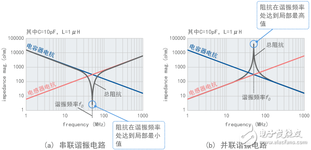
As shown in Figure 2, the resonant circuit is divided into two types: series resonance and parallel resonance. According to the calculation example in Figure 3-2-2, series resonance minimizes the impedance (theoretically zero), while parallel resonance raises the impedance to the highest value (theoretically infinite).
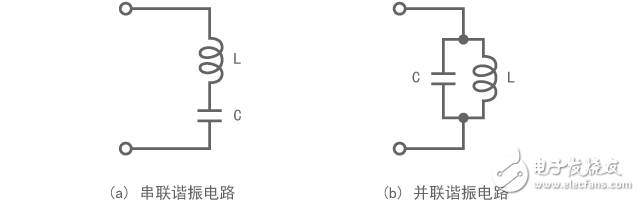
Figure 2 Series resonance and parallel resonance
(The figure shows the magnitude of the reactance on the number axis)
Figure 3 impedance of the resonant circuit
(3) The reactance offset is zero
As shown in Figure 3-2-3, the magnitude of the inductor reactance and the capacitor reactance become equal at the resonant frequency, and the two cancel each other out, and the sum of the sums is zero.
Figure 3-2-3 illustrates the case of series resonance; if it is a parallel resonance, the reactance is replaced by susceptance (the imaginary component of the admittance), and the susceptance is cancelled to zero at the resonant frequency. Therefore, the impedance rises to the highest value, which is easy to understand.
(4) Resonant frequency
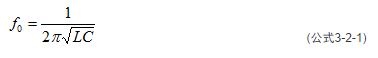
Whether it is a series resonance or a parallel resonance, the resonance frequency Æ’0 can be estimated by the following formula. In the example of Figure 3-2-2, Æ’0 is approximately 50 MHz.
(5) Resonance Q
The resonance intensity can be expressed by an index Q (quality factor). A higher Q indicates a stronger resonance. The index Q is also used as an index to represent the performance of the capacitor and inductor. There is such a relationship: When a capacitor or inductor having a large Q value is used, the Q value of the established resonant circuit is also large. How to estimate the Q value will be explained in Section 3-2-5.
(6) Self-resonance of capacitors and inductors
When a capacitor or inductor is used in the high frequency range, the capacitor or inductor itself causes resonance at a specific frequency due to its inherent parasitic component. This is called self-resonance. Self-resonance will be further described in Chapter 6.
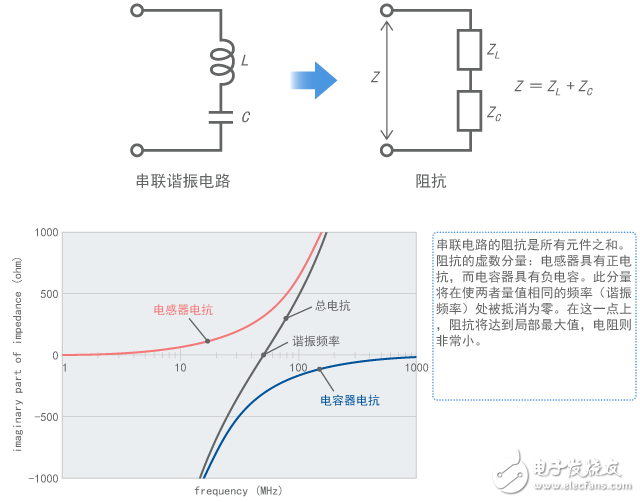
Figure 4 Mechanism of series resonance to minimize impedance
Alps Hollow Shaft Encoder,Hollow Shaft Encoder,Encoder For Medical Coding,Encoder Wiring Diagram
DA CHENG MINGHUA LIMITED , https://www.alpsswitch.com