
The popularity of high-performance embedded portable devices puts new demands on the design of embedded display systems: high performance, low power consumption, small size, good portability and ability to work in a variety of lighting environments. The embedded display system designed in this paper provides a solution for the development of display systems for such portable devices, which not only satisfies the high performance required by high-end embedded devices, but also maintains low power consumption under high-brightness display conditions. For high-end PDAs, portable media players, handheld navigation devices, portable medical and test equipment.
The proper choice of the main components is the key to achieve the above design goals. The embedded microprocessor Samsung S3C2440A (also the LCD controller of this display system) is mainly used for high-end embedded devices. It uses ARM920T core and the maximum operating frequency is 533MHz. , including 3 channels of asynchronous serial port, SDRAM controller, I2C bus interface, USB master, slave unit device interface, camera interface, AC97 audio codec interface, touch screen interface and LCD controller and many other on-chip peripherals, low power Consumption, cost-effective. In addition, Sharp's 3.5-inch transflective TFT-LCD LQ035Q7DH01 uses Advanced-TFT technology, which uses a metal film of a conductive trace of an interconnected thin film transistor as a reflector to return incident light through the LCD matrix, thereby enhancing strong ambient light. The brightness is low while maintaining low power consumption; HR-TFT (high-reflection liquid crystal) function in bright places, and transmissive liquid crystal function with built-in backlight in dim environment, which can be used in strong sunlight Work in an all-black environment. Its screen resolution is 320×240, and it can display 262,144 colors with 18-bit data signals.
Because embedded Linux has good stability and platform portability, and open source code at the same time, the cost is low. This article uses embedded Linux as the operating system. The software development environment uses the Linux 2.4.20 platform, and the cross compiler is arm-linux-gcc 2.95.3, which completes the driver development for the LQ035Q7DH01 display.
Display system hardware circuit
1 LCD controller circuit
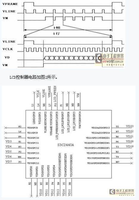
The LCD controller is used to transmit image data and generate corresponding control signals. The S3C2440A LCD controller can support up to 4K color STN screen and 256K color TFT screen, support various LCD screens at 1024×768 resolution, and have LCD-specific DMA. The control signals generated by the S3C2440A mainly include a frame sync signal VFRAME, a line sync signal VLINE, a pixel clock signal VCLK, and a data output enable signal VM. S3C2440A has VD[0:23] a total of 24 RGB data lines, the data format is different, the wiring method is different, this article uses the RGB565 mode. The control signal and data signal timing are shown in Figure 1.
The LCD controller circuit is shown in Figure 2.
2 timing and data matching circuit
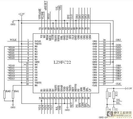
Since the LCD controller of the S3C2440A and the LCD panel LQ035Q7DH01 cannot match the data format and display timing, you need to select a timing control IC or use CPLD to map the data interfaces of different data formats. Due to the large size and high cost of the CPLD, it is usually only used when the circuit needs to be flexibly configured. The timing control IC of this paper selects Sharp's LZ9FC22, which is small in size and stable in performance, and is dedicated to QVGA screen TFT-LCD. This is an 18-bit (R6G6B6) controller. Since this article uses the RGB565 16-bit mode of operation, the chip input pins R0 and B0 are grounded. The pin SIZE is used to select the LCD screen type, and when it is low, it is a 320×240 type screen. When connected to a high level, it is a 240×320 type screen. In this paper, the LCD is a 240×320 type screen, so this pin is connected to a high level. Pin VRVE is used to select the LCD frame scanning direction. When the low level is connected, the scanning direction is from top to bottom. When connected to the high level, the opposite is true. Pin HRVE is used to select the LCD row scanning direction. When connected to low level, the scanning direction is from right to left. When connected to a high level, the opposite is true. In order to facilitate the flexible configuration of different users according to their respective needs, this paper designed an LCD scanning direction configuration circuit, as shown in Figure 3. Each pair of resistors R32, R34 and R33, R35 selects one access circuit for each pair as needed, thereby setting the high and low levels of pins VRVE and HRVE. To configure the LCD frame scanning direction from top to bottom, the pin VRVE should be low. In this case, only the resistor R35 should be connected in the circuit, and the resistor R33 should not be connected. If you want to configure the LCD frame scanning direction from bottom to top , the pin VRVE should be high level, in this circuit only need to access the resistor R33, the resistor R35 does not need to be connected, the LCD line scan direction configuration is similar. In this paper, the LCD uses the scanning direction from top to bottom and from left to right, so the resistors R32 and R35 are connected to the circuit and the positions of R33 and R34 are empty.
Figure 3 timing and data matching circuit
3 multi-channel voltage generating circuit
Digital and analog circuits are integrated in the LCD panel, and external digital and analog voltages are required. In addition, in order to complete the data scanning, the TFTs need to be turned on/off in turn. When the TFT is turned on, data is loaded to the display electrode through the source driver, and the voltage difference between the display electrode and the common electrode is applied to the liquid crystal for display, so it is necessary to control the turn-on voltage, the turn-off voltage, and the voltage applied to the common electrode of the LCD. .
This article uses Panasonic's low dropout voltage linear regulator LM1117DT-3.3 chip to generate the digital voltage required for timing control IC and LCD. The MAX1664 active matrix liquid crystal display power chip from MAXIM is used to generate other voltages. The +5V input voltage required by the two chips is provided by 220V AC through an AC/DC switching power supply. The MAX1664 integrates two DC-DC converters, of which DC-DC1 provides an output voltage from the input voltage to +5.5V, DC-DC2 is a positive and negative voltage dual output, and one can provide input voltage values ​​to + The output voltage of 28V, the other channel can provide 0~-10V output voltage. For small TFT LCDs such as the LQ035Q7DH01, the MAX1664 provides an efficient regulation voltage. In addition, the MAX1664 is a high-power switching power supply. Pay attention to the connection of the power supply circuit and the connection of the bypass capacitor. The chip bypass terminal IN and INP are separated by a 33Ω resistor, as shown in Figure 4. D4 ~ D6 in Figure 4 should use high-speed Schottky diode, and because the DC equivalent resistance of the inductor has a great influence on the conversion efficiency, L3 ~ L4 should use the inductor with low equivalent resistance, in order to reduce noise radiation, Shielded inductors should be used. The wiring of the circuit board should be carefully operated, and the connection of the grounding point should be handled carefully, otherwise the stability of each output voltage will be affected.
Figure 4 Multiple voltage generation circuit

4 display system overall structure block diagram
The LCD controller first reads out the image data from the display buffer of the memory SDRAM and converts it into the data format of RGB565, and then sends the data signal and the control signal generated by the LCD controller to the timing control IC LZ9FC22, timing control IC. The data signal and the control signal are converted into a format compatible with the LCD and sent to the LCD, and finally the LCD displays the image on the screen. It should be noted here that when wiring the circuit board, the connection distance between the LCD controller and the LCD screen should not be too long, preferably not more than 50cm, otherwise it is prone to display errors. The overall structure of the display system is shown in Figure 5.

Figure 5 shows the system block diagram
Conclusion
The embedded display system designed in this paper shows a brightness of 100 nits. The power consumption of the module is less than 365mW in the case of high brightness of the LCD, which overcomes the contradiction between the high brightness of the general TFT-LCD and the high power consumption, and the hardware due to the design. The driving circuit only needs the LCD controller to give the frame synchronization signal, the line synchronization signal, the pixel clock, the data enable signal and the RGB data signal, so that it has great flexibility for porting to different platforms, and is highly practical. .
Edit: Nizi
IP65 Floor Standing Touch Kiosk integrates a Touch Screen Monitor, pc , a floor stand base and some other external devices together to use.
The monitor Supports IP65 surface water proof and dust resistance while keeping a compact and narrow bezel design.
Touchwo solutions include a full-range of touchscreens including IR Infrared touch, PCAP touch and stand bases.
There are many stand bases to fit for different size of monitors.
Simple installation: power a key switch, dispense with on-site installation and
commissioning.
Ip65 Floor Standing Touch Kiosk
Lcd Kiosk,Touch Screen Computer Kiosk,Freestanding Kiosk,Ip65 Floor Standing Touch Kiosk
Guangzhou TouchWo Electronics Co.,Ltd. , https://www.touchaio.com