
Introduction
This article refers to the address: http://
In order to reduce carbon dioxide emissions and improve fuel efficiency, automakers are now actively working toward reducing weight in vehicles. As a result, designers are constantly looking for new technologies and design tools that can help them reduce the weight of their harnesses. In order to remain competitive in the market, automakers must also reduce warranty costs and improve user satisfaction. Therefore, car designers are facing the challenge of finding a new way to reduce the weight of the car without sacrificing system reliability.
This industry trend has led designers to revisit the methods they use to protect automotive power functions that are compromised by large fault currents. Although the use of decentralized wire harness technology and PPTC (Polymerized Positive Temperature Coefficient) devices for overcurrent protection has significant weight advantages, many manufacturers still use conventional fuse protection techniques, resulting in difficulty in reducing wire harness weight.
This white paper describes the benefits of using a decentralized architecture and Tyco Electronics PolySwitch devices to protect automotive wiring harnesses and compares them to traditional fuse protection centralized architectures. This article also describes the features of PolySwitch devices and provides specific application examples for using these devices in a decentralized architecture that will facilitate the development of lighter, more flexible, and more reliable harness protection designs.
Harness protection trend
Although distributed harness protection using PPTC devices was introduced as early as the 990s, OEMs have been slow to adopt this approach. In fact, as electrical and electronic functions in modern vehicle applications continue to increase, automotive wiring systems have become larger, heavier, and more complex than ever before.
In addition to changing the resistance of traditional design methods, the benefits of using PPTC devices have been constrained by the thick wires that have traditionally been used in vehicles. In the past, mechanical strength specified that the thinnest wire used in a vehicle was 0.35 mm2 (22 AWG) and could carry a current of 8.0 A. This limitation offsets the advantages of using PPTC devices for small current signal circuits such as <8A. Nowadays, the new wire material process has been able to carry larger currents on smaller diameter wires, such as 0.3 mm2 (26 AWG) wires that can carry up to 5 A. This advancement will result in more weight savings if combined with the PPTC decentralized protection architecture.
A study of mid- to high-end passenger cars, a decentralized architecture, and Tyco Electronics' PolySwitch devices showed that only one copper wire saved about 50% of its weight. In addition, system reliability and design flexibility are greatly improved due to the decentralized architecture and the replacement of fuses with resettable PolySwitch devices.
Car harness protection
In a car, current flows through various primary and secondary wire assemblies distributed throughout the vehicle to different electrical loads. For a 2 V battery system, the circuit typically carries a current of 0. 0A to 30A at a system voltage of 4 V (24 V battery system in most trucks and buses with a system voltage of 28 V). Harnesses must be protected from damage due to catastrophic thermal events such as short circuits.
Designers face the challenge of adding circuit protection devices, protecting potential overload conditions in electrical systems, while reducing overall cost and weight. Since typical vehicles typically contain hundreds of circuits and more than one kilometer of wire, complex wiring systems can plague traditional circuit design methods and lead to unnecessary ultra-safety standard designs.
Traditional approach: centralized architecture and fuses
As shown in Figure 1a, the traditional protection scheme for automotive wiring systems used to be centralized and distributed multi-load fuse technology. In this type of centralized (or "star") architecture, each function requires a separate wire. If a single wire supports multiple functions, then this wire and its fuse must also carry the sum of the currents of all these functions. When more and more circuits are issued from the electrical center, it has become almost impossible to arrange the access lines of all the wires in a single junction box and arrange the junction box in a position convenient for driver maintenance. As a result, system designers have resorted to some wire harness designs that have reduced some of their final utility, such as:
1. Combine the load in one circuit, sacrificing wire specification optimization and fault isolation;
2. At the expense of cost, place the electrical center in a location that is accessible only to trained professional service personnel;
3. Routing back and forth between various functional systems increases wiring length, specifications, and cost. For example, because fuses must be easy to maintain, traditional door modules may provide separate power feeders for window, door lock, LED, and mirror functions, each with a separate fuse in the junction box. protection.
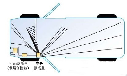
Figure 1a. Typical centralized architecture
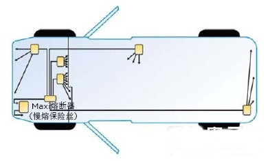
Figure 1b. Typical decentralized architecture
The vehicle's traditional centralized wiring protection architecture relies on a limited number of large-size fuses to protect the various circuits from damage due to high current fault conditions. Although fuses are relatively inexpensive, they must be replaced as a single-use device once burned. This feature means that the fuse must be installed in a fuse box that is easily accessible—a requirement that dictates the system architecture and forces the package and system layout to make concessions. Fuses also have nominal current ratings of 2A to 30A in the same form factor, and they are often replaced with fuses larger than the design value or fuses that jump out of the circuit (when used in delocalized modules).
Alternative: Decentralized architecture using PolySwitch devices
This is an optimized harness protection scheme with a tree-like hierarchy where the main power "trunk" is divided into smaller "branch"s that provide overcurrent protection at each node. This architecture allows for smaller, more space-saving wires, reducing vehicle weight and cost. It also helps improve system protection and provides fault isolation, which greatly increases reliability. Figure 1b shows a schematic of a decentralized architecture in which multiple junction boxes (represented in yellow) are powered by the power bus. Each wire that comes out of the junction box, receives power, and goes to a different functional device can be protected with a resettable circuit protection device. Figure 2 is a simplified version of a partially distributed architecture in which each junction box either powers one module directly or another node module that powers a peripheral load.
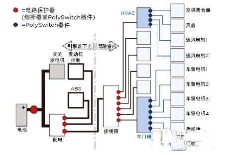
Figure 2. Details of a partially distributed automotive wiring harness architecture
A decentralized electrical system architecture can be implemented using PolySwitch overcurrent protection devices. Due to the availability of automotive-grade devices and the reliability that can be expected on relays, these modules can be switched (switched) and protected from their own output loads and installed in locations that are inconvenient to service.
Since the PolySwitch device eliminates the need for a user-accessible central fuse holder for power distribution wiring, it can be routed according to the most direct path between the power supply and the load. This shortens the length of the wire and reduces the wire size, which not only saves a lot of space, size and cost, but also reduces various terminals, contacts, switches and electronic drive circuits used in the vehicle. In addition, the decentralized architecture reduces the number and size of connectors and junction boxes required. For example, by using a PolySwitch device in the door module, a power feeder can be used, saving wires, reducing cost and junction box size.
Table. Comparison of wire weights for traditional fuse and distributed harness protection architectures. Wire weight calculation based on copper density 8.96x10⁻⁶kg/mm3
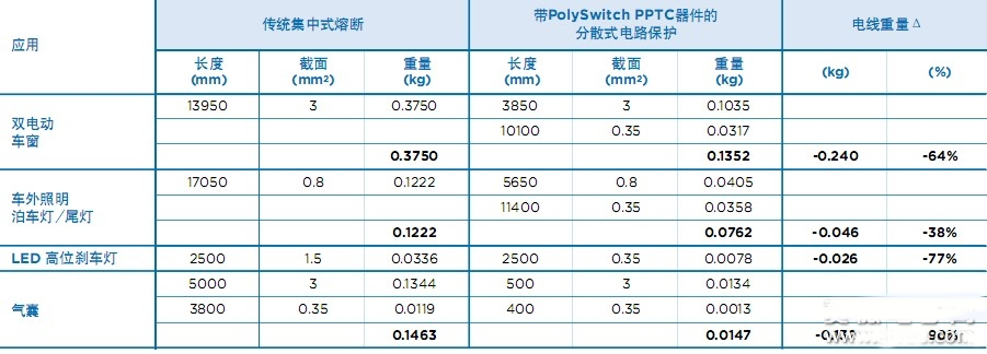
Table 1 shows the weight savings of a decentralized architecture and PolySwitch devices compared to traditional fuse protection techniques. (Note that as mentioned earlier, the minimum wire size used in this example is 0.35 mm, while in some applications smaller wires are available.)
The use of a resettable circuit protection device that does not require driver maintenance provides designers with a number of solutions that can be used individually or in combination. A single junction box located in the instrument panel may still be in use. Unlike fuses, fuses must be installed in the upper part of the junction box for easy replacement, and PPTC devices can be embedded in the junction box or mounted on other surfaces of the junction box, reducing the area requirement on the front side, as shown in Figure 3. Show.
In addition, by placing the protection device close to the connector, the track length can be shortened and the size of the junction box can be reduced. You can also choose to divide the junction box into smaller units and re-select their position around the body, regardless of whether it is easy for the user to access. In this case, PolySwitch devices can help designers implement electrical structures that more closely reflect the optimized tree structure and its attendant benefits.
PolySwitch devices come in a variety of form factors to facilitate various interface options with junction boxes or electrical components. Cartridge (through-hole) devices and surface mount devices make them suitable for mounting in fuse boxes or modules that use printed circuit boards. Strap devices can be used for metal electrode connections.
The new generation of PolySwitch chip devices can also be inserted into junction boxes like plug-in fuses or bimetal breakers. While these devices can be automatically reset without the need for the user to replace them, the chip device outline allows the designer to replace the fuse or bimetal without waiting for the next redesign of the junction box.
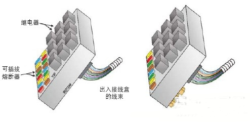
Figure 3. Comparison of traditional junction box design (left) and reduced junction box design (right)
Improve reliability
In addition to saving weight and cost, the reliability of circuit protection devices is one of the key factors in determining how to protect the vehicle's electrical system. Compared with fuses, PPTC devices have obvious advantages. They can withstand various overcurrent events in the automotive environment—including such things as wire insulation wear and loose terminals in the connector, without causing device burnout. Or downgrade.
PolySwitch devices are fabricated from conductive fillers, such as carbon black, which provide conductive paths through the device. Such devices have lower resistance characteristics under normal operating conditions, and when excessive current flows through the device, the temperature rises and the crystalline polymer changes to an amorphous state.
As shown in Figure 4, this transient causes the polymer to expand and the conductive path within the conductive polymer to break. During the time of the fault, the device resistance typically increases by three orders of magnitude or more. The increased resistance helps protect the equipment in the circuit by reducing the current flowing under fault conditions to a lower steady state level. The fault is removed and the device will remain in the locked (high resistance) position until the circuit is recharged; during this time the conductive composite material gradually cools and crystallizes, returning the PolySwitch device to a low resistance state and affecting it. The device is restored to normal operation.
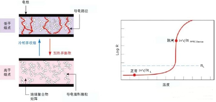
Figure 4. PolySwitch helps protect the circuit by responding to overcurrent or overtemperature conditions by transitioning from a low-impedance state to a high-impedance state.
Technical comparison
Since fuses are single-purpose devices, the heat capacity is low, and in some applications they must be selected to "increase" specifications or to specify an elevated current rating to prevent "nuisanceblow". In contrast, the thermal capacity and trip temperature of a PPTC device allow for closer matching of the device's damage current, thus reducing the activation time in lower current fault events. In some configurations, the PPTC device activates faster than the fuse activation at the specified fault current.
"Niusance blow" is often caused by inrush currents associated with specific electrical components present on the powered equipment. For example, intermittently operating motors are often designed to operate for a limited period of time. In general, if the time to run this product exceeds the maximum limit of the design, it will cause blockage, overheating and eventually failure. It remains powered when a fault condition occurs, either because of poor contact or by user misuse. To prevent overheating, the circuit protection device must be “tripped†quickly—but not shorter than the specified time—to avoid misoperations with the user.
The main advantage of using a PPTC device is that it can be specified that the trip current of the device is much lower than the normal operating current of the motor, but the trip time can be specified as several times the full system duty cycle to prevent false tripping.
When exposed to a fault condition that exceeds the operating current of the system, the fuse will reach an undesired temperature, but not enough to cause timely activation. In contrast, the activation speed of the PPTC device is relatively fast and the temperature is stable, so the fault current has little effect on its surface temperature.
Mean Time Between Failure (MTTF) is another important consideration in choosing a circuit protection device. The MTTF is calculated the same as the MTBF (mean time between failures). The difference is that MTBF refers to a repairable system, that is, the time between one repair and the next. The MTTF is used in situations where it cannot be repaired, such as a single component.
Table 2 compares the MTTF of PolySwitch devices with other circuit protection devices according to the telecom industry's reliability prediction standard, Bellcore TR332.
Industry standards also play an important role in designing the electrical/electronic systems of vehicles. AEC-Q200 - Stress testing standards for passive components, including PPTC device testing requirements for automotive environments. The test protocol includes a series of electrical and environmental stress tests that require electrical verification before and after each force. The electrical verification test is designed to verify that the device meets the performance requirements for resistance, trip time, and hold current at three temperatures (-40 ° C, 25 ° C, and maximum temperature).
Tyco Electronics' PolySwitch devices have robust characteristics required by the automotive environment and meet stringent test procedures that define performance limits before and after stress testing. The Tyco Electronics PS400 specification for automotive grade device qualification covers the AEC-Q200 standard and incorporates the physical, functional, environmental, electrical, and mechanical requirements specified in various ANSI, ISO, JEDEC, UL, and military standards.
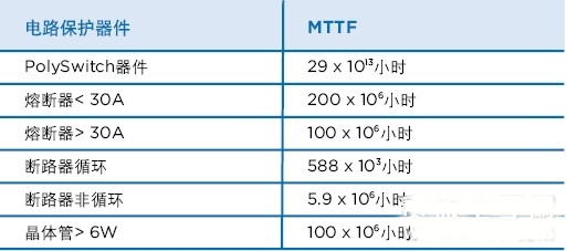
Table 2. MTTF comparison of circuit protection devices in telecommunications applications
Apply PolySwitch devices and distributed architecture
Distribution decentralization offers many opportunities for innovation in electrical and electronic system architectures. Several examples are given below to illustrate the role of resettable circuit protection.
Reduced wire, terminal, connector and switch dimensions for DC motors and actuators
Due to the high stall current, the motor circuit in a typical centralized configuration is typically protected by a large size circuit breaker or fuse. This design must use a thicker wire, so the interface pins and connectors must be larger. The result is that the excuse package area must be larger, creating space and weight issues. In addition, since the motor of the rear door window, the door lock and the rear cabin electric antenna are far from the control switch, the motor feeder may be long and heavy.
In contrast, the decentralized architecture allows designers to mount PPTC devices on switches, relays, or electronic drive circuits that control the motor, providing a reasonable distribution of circuit protection devices. The PPTC device also limits the current flowing through the feeder circuit to the protected motor. This will greatly reduce the feeder specifications. Take the electric window as an example. If the upstream circuit breaker is used for protection, the feed generally uses 3.0 mm2 wire. If a PPTC device is used in the motor control switch, the feeder specification can be reduced to 0.8mm2, which is determined by the voltage drop.
Wire sizes are reduced and smaller terminals, interface connectors and switches can be used. In addition, fine-tuning (micro-control) circuits can also use unprotected transistors with lower cost and lower power in the driver circuit. Ultimately, the cost of the wire assembly and its associated hardware is greatly reduced. The use of small gauge wires reduces the size of the wiring harness and improves the flexibility of the wires. Improved the appearance of the wiring assembly. It also reduces the external force required to install the wires in the vehicle, thereby reducing the likelihood of damage during installation. The following examples illustrate the usefulness of this benefit.
Shortened feeder length in airbag safety circuit
Automotive airbags are the best illustration of the strict requirements imposed on safety circuit wiring assemblies. These devices include spliced ​​signal lines, dedicated circuit connectors, shorting bars on the connector interface, and redundant feeders.
In a typical centralized harness protection scheme, the feeders in the airbag assembly pass from the ignition switch to the switch to the fuse holder to the airbag control module in the center of the instrument panel. The decentralized protection scheme can reasonably place the PPTC device on the steering column base. This allows the feeder to be connected directly from the ignition switch to the airbag control module. This way the feeder is shortened by more than one meter.
Reduces the wire weight of the trailer traction light circuit
Bare use, maintenance inconsistencies, and short circuits and overloads caused by water ingress make trailer traction circuits a high-risk application. In order to improve reliability, the trailer traction lamp circuit generally uses a fuse and a feeder line independently. In this design, all of the lights are typically protected by a single fuse installed in the central fuse holder.
However, in a decentralized architecture, PolySwitch devices can be mounted on a lamp assembly, connector or lap block, effectively reducing three fuses, one relay, three long wires, and associated connectors. This solution also simplifies the design of brakes, directions and hazardous modules and switches. Figures 5a and 5b compare a traditional centralized design with a decentralized protection design that uses a PolySwitch device to protect each vehicle light circuit at each corresponding junction node.
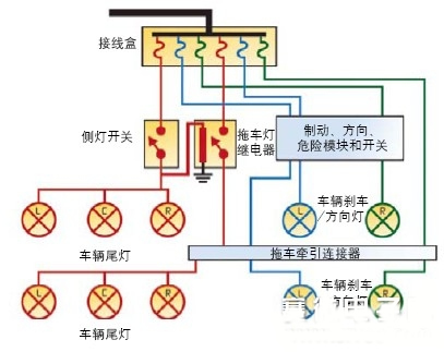
Figure 5a. Traditional centralized protection scheme
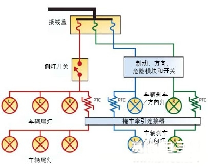
5b. Decentralized protection scheme using PolySwitch PPTC devices
By using a decentralized architecture, vehicle wiring is protected by PolySwitch devices in the event of a short or overload. The PolySwitch device automatically resets when the trailer is disconnected from the power source. Unlike traditional circuit protection, this design does not require the driver to find and replace a burnt fuse in the event of a transient overload.
In addition, the wires connecting the lights to the junction node only need to carry the current flowing to the lamp - and the design of the shared feeder and its fuses must carry the sum of the currents flowing to all the lamps. The most important point is that no matter which over-current fault occurs in the trailer traction lamp circuit, only this circuit will be affected, and other lights will work normally.
Reduced wire specifications for LED mid-high brake light circuits
The low power consumption and design flexibility of light-emitting diodes (LEDs) make them increasingly popular in lighting circuits, including mid-range high-position brake lights (CHMSL). The benefit of replacing an incandescent lamp with an LED in this application is that it can be easily routed in a roof lining and a connection that is not easily bent near the hinge using a small gauge low current conductor, as shown in FIG. Protecting LED CHMSL lighting applications with PolySwitch devices and distributed architecture increases design flexibility, reduces wire count and weight, and increases reliability.
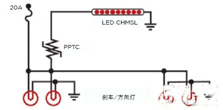
Figure 6. Distributed harness protection in LED CHMSL applications
in conclusion
The decentralized architecture with PPTC overcurrent protection can significantly reduce the weight of the car. Although the decentralized approach has matured for many years, the advantages of this approach over traditional fuse protection techniques have been highlighted until recent availability of thin wires capable of carrying large currents and new industry incentives emerge.
The use of Tyco Electronics' PolySwitch PPTC devices in a decentralized harness protection scheme offers many important design advantages. PolySwitch devices help automotive designers reduce wire length and weight while increasing design flexibility and system reliability due to their functional recovery, low resistance characteristics, and rated power.
It`s quite small and cute .No matter what you are looking for business or personal gift. These series mini USB is a good choice . You also can attached the keychain on it. So easy to carry to everywhere. Multi-color available in Red,blue,green,sliver, customized color available too.Contact with us freely for more details.
Mini USB Stick,Mini USB Flash Drive,Mini Pen Drive,Mini Flash Drive
Custom Usb Gift company limited , https://www.customusbgift.com