
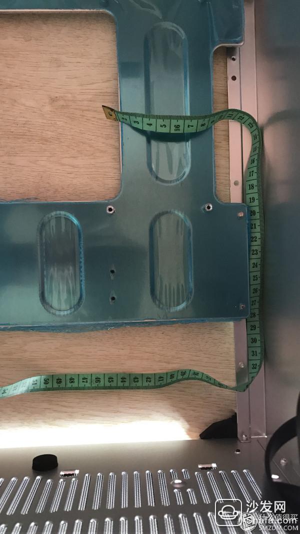
Recently, the company had to deploy a batch of computers and chose the chassis of Qiao Sibo C3. This chassis has a back line space, but the designers of brain damage actually did not stay in the back hole. I measured it myself and used a custom silver plated module line. Can go back line, so Taobao asked a few custom lines, the cheapest custom line is also close to 200 yuan, because the number is a little more, so it is not worthwhile. Checked the tutorial on the self-made module line on the Internet, looked at the following should be made by themselves, so immediately ready to go dry procurement materials.
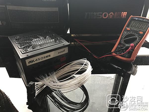
The power I bought was the game AK450, because office computers use integrated graphics, so I chose the cheapest one. 211 computer festival full 100-20, superimpose 199-10 coupons, actually paid 189 yuan to hand. Should be the cheapest full-module power supply, this price is still 80PLUS certification, but also what bike? As for the story of the red star shining, it has been N years and it has been awkward.
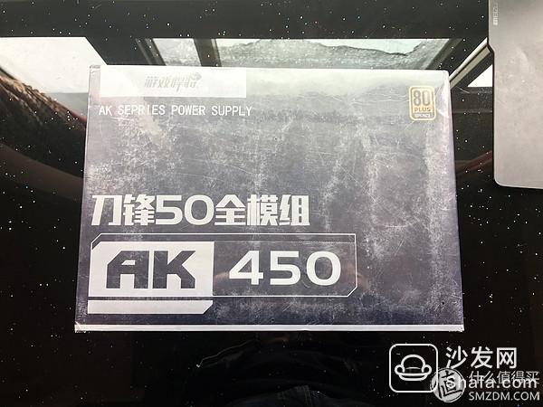
 The game player (FORGAME) rated power 450W blade 50 full module AK450 power supply (80PLUS full voltage bronze medal / full module / Taiwan-based capacitance) 199 yuan game player blade 50 AK450 full module power supply using dual-transistor forward topology In the current low-cost high-conversion power supply, the LLC half-bridge and the double-transistor forward are more common. Compared with the LLC half-bridge structure, the two-transistor forward efficiency is lower, but the stability and the electrical life of the two-transistor forward are better than those of the LLC. Stronger, so the double-tube forward on the low-end low-power power supply products is more reliable. This AK450 full module power supply through the 80plus bronze certification Jingdong direct link to encyclopedia
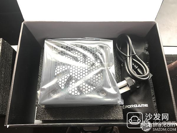
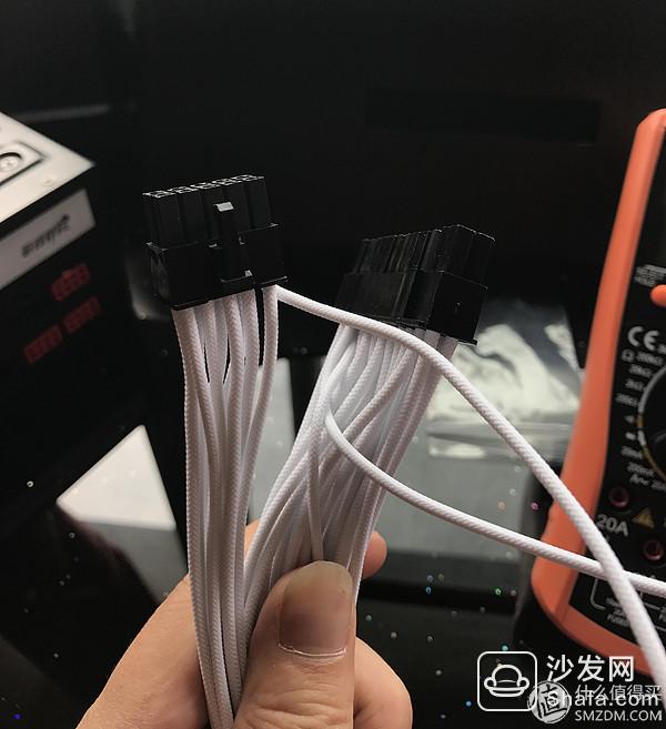
 The package can also be very gas, the original module line has 5, looks good, but the hardness is hard, and the length does not meet my requirements.

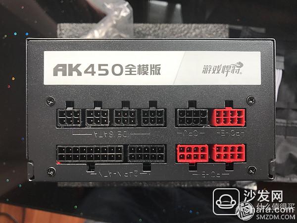
Module hole position, hard disk power supply (6PIN)*4, CPU power supply (8PIN)*1, PCI-E graphics card power supply (8PIN red)*3, motherboard power supply (10PIN+18PIN)*1.
Doing the module line may sound complicated, but actually it is difficult to do the motherboard power supply, AK450 has to connect 26 lines in total, can not be wrong, wrong fear of BOOM ~ ~ power is to be followed, the motherboard CPU is burned out, then Big loss. The number of other lines is up to 8, and you can do it against the original lines.
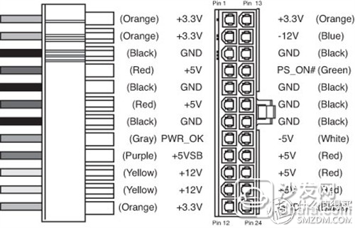
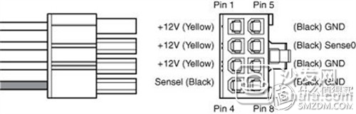
Before the production, we must first understand the ATX power interface definition, this is the Intel specification, all power is the same. See below:
Motherboard 24PIN definition:
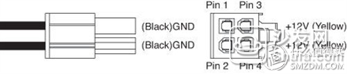
CPU 4PIN definition:
CPU 4+4PIN definition:
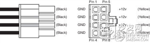
Graphics card 6PIN definition:
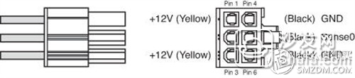
Graphics card 6+2PIN definition;
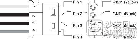
D port definition:
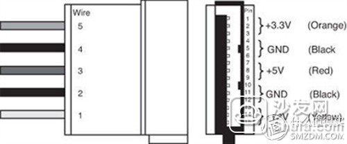
SATA port definition;
In order to let everyone know more clearly, take the board 24PIN this interface as an example.
The definition is as follows:
In other words, all power supplies plug into the motherboard is the same standard, but different brands of power plug modules may not be the same, this is the difficulty of production.
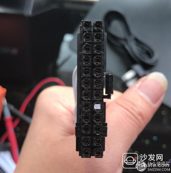
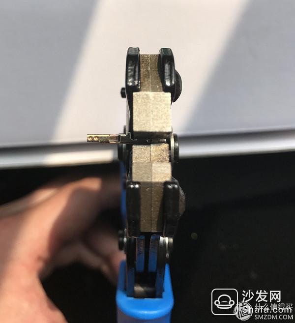
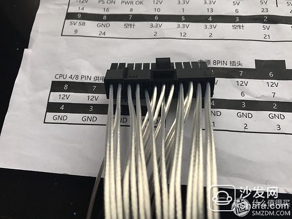
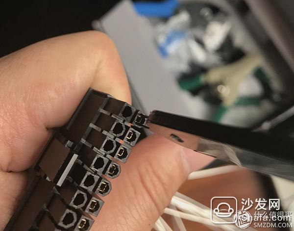
The following figure shows the 18PIN+10PIN header of this power plug module:

In total, there are 28 holes. There are 2 blanks. 26 lines are to be inserted.
So how to determine the line sequence? There are two ways:
First, pull the original module line one by one, visually see the corresponding relationship, see a record one.
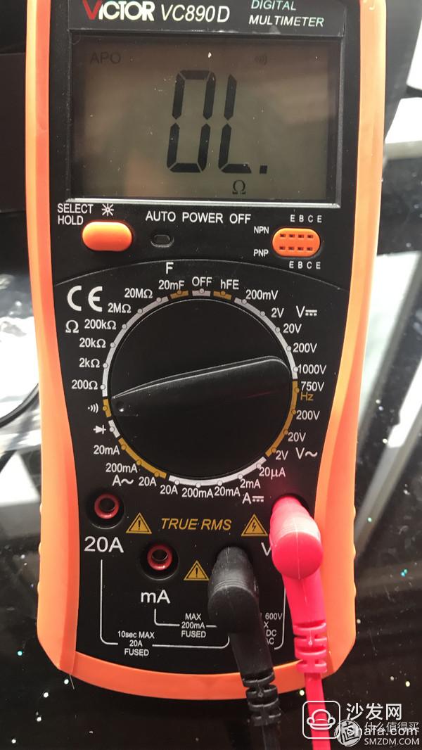
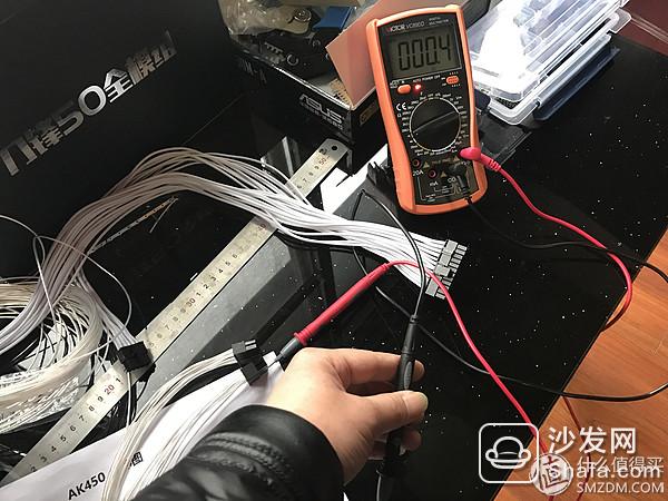
1. Measure with a multimeter and transfer the multimeter to the next gear. If the two wires are connected, the multimeter will ring and record it.

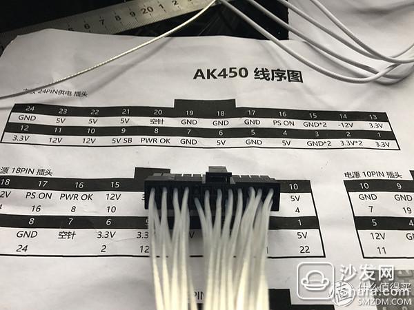
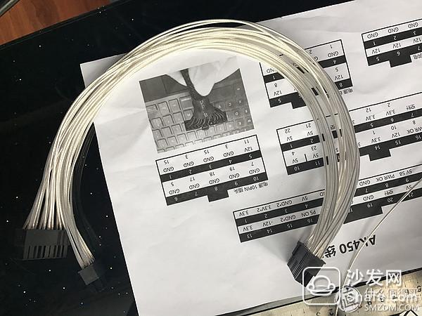
The following is my own test AK450 line sequence diagram (mainboard power supply + CPU power supply), the lower right corner is the perspective diagram, which means that from this point of view. In order to facilitate the control of the back of the line, I gave it out. We must pay attention to seeing that some holes are to be inserted in double lines.

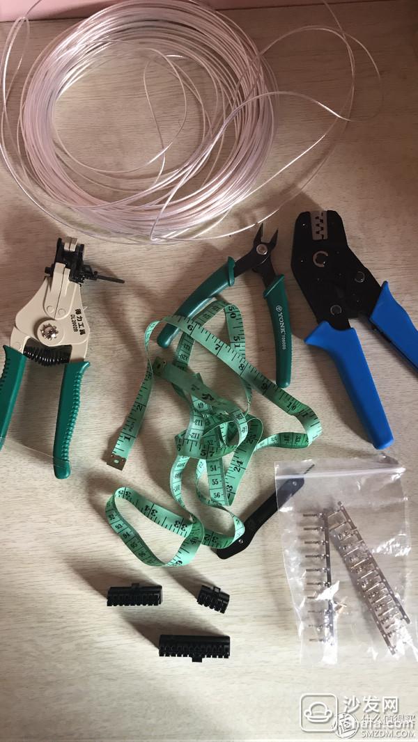
After the line sequence is determined, the module line can be started. Let me say what tools and materials are needed.
Tool list: crimping pliers, stripping pliers, diagonal pliers, withdrawal needles, tape measure.
Crimping pliers: used to press the terminal, many online tutorial recommended OPT this brand, more than 100, I did not buy this, bought a general 70. It is also very easy to use after becoming skilled.
Stripping pliers: Note that there are a lot of styles, and this style I bought should be the best one. The price is not expensive, 20 包邮.
Diagonal pliers: 10 dollars for trimming, of course, you can also use scissors.
Line withdrawal needle: In case the wrong terminal is inserted, this withdrawal line can be used.
Tape measure: Measure the length of the line you need in the chassis.
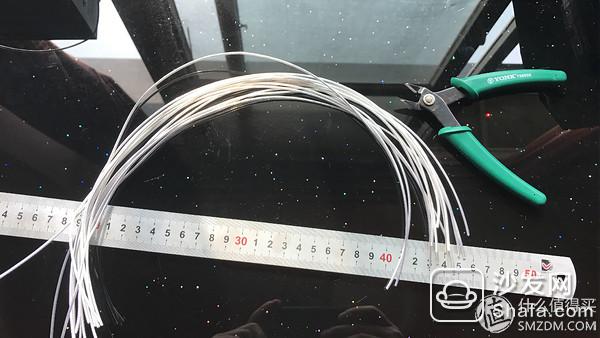
Material list: silver plated wires, terminals, and plastic shells. The quantity needed was bought according to my own needs. I used 18AWG silver plated wire, about 160 rolls and 95 meters. Jessica's terminals and plastic shell.
The first step in making a module line is to measure the length of the line you need to make and record it.
CPU power supply back line, probably need 75CM, because the first time to do the line, it does not matter long, short to waste, so I did 80CM.
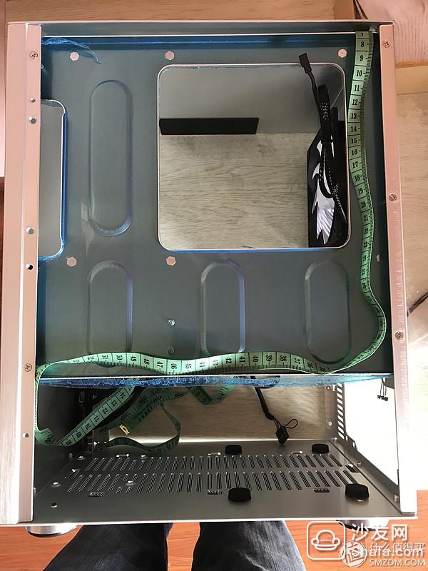
The chassis main board power supply back line cover is not good cover, so think of the next, go ahead, hide the line behind the hard disk rack, walk along the side, can not see. It takes about 45CM here.
Here I only talk about the most difficult method of motherboard 24PIN power production, this you can get, the other line is not something ~
I bought this module power supply motherboard power supply is a total of 26 lines, I first cut a 45CM line out, and then control a one-time cut 26, do not cut a one, so slow, one-time batch It's much more efficient.
After the wire is cut, the wire is stripped. When the wire is stripped, pay attention to this stripping tool and fix the card position. Each time is the same length and it is neat.
The recommended stripping length is 3-5mm. In the same way, all lines are stripped at once.

The next step is to press the terminal. This is a bit difficult. At the beginning, I crushed the three. Later, I was skilled in mastering one skill and not bad. Here's how to press the terminal:
For the convenience of explanation, I will number the three legs of the terminal as 1, 2 and 3 respectively.
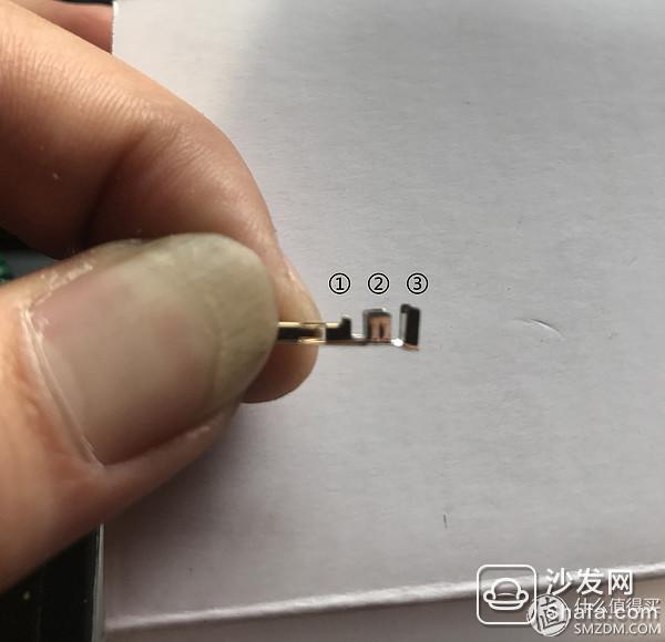
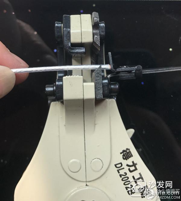
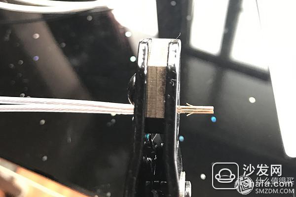
First put the ends 2, 3 inwards with a pressure, which is better to put into the crimping pliers. Put the No. 2 and No. 3 feet in the crimping pliers (note that pin No. 1 must not be put in the crimping pliers)
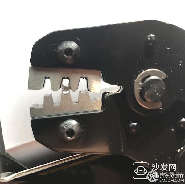
Then put in a stripping line, press the 2nd foot, press the 3rd foot. Adjust the position of the line, and the stripped line is completely covered by foot 2, but do not exceed foot 1, gently press down, fix the position of the line, and then press the mold into a hard one-time, see the following figure:

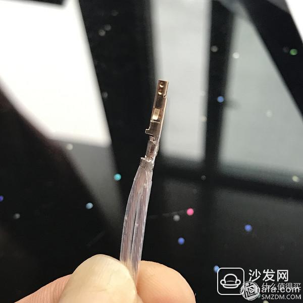
The following enlarged view of the crimped terminal:
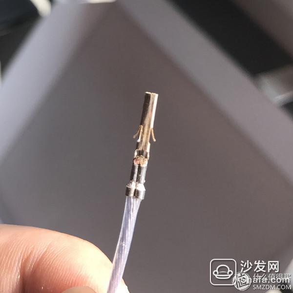
Make both ends well.
This part of the pressure line is the most critical part. To make everyone understand more clearly, I will elaborate on the following figure:

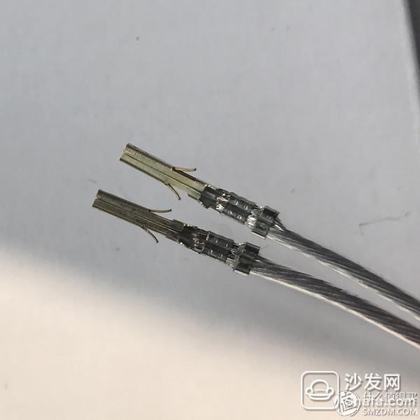
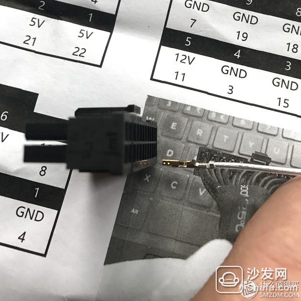
Double line production method:
Put the terminal into the crimping pliers first, press down a little to fix the terminal, put the two lines into the terminal, gently press down to fix the position of the line, and then press it down with force.
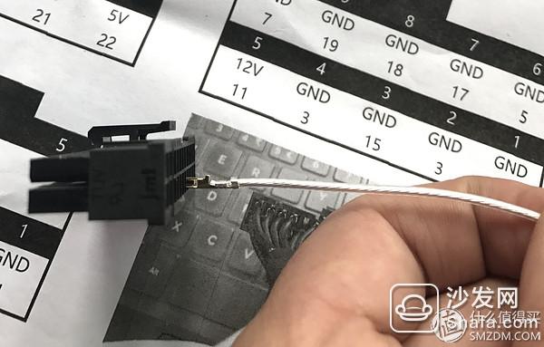
After pressing the two-wire terminal, the other one is pressing two separate terminals respectively. Do not press both wires at both ends. See the figure below:

After the terminals are fully pressed, they are inserted into the plastic case. It is recommended to print out the line sequence diagram and compare them with each other.
The insertion method is the foot upwards, as shown below:
First plug in the motherboard 24PIN power supply, pay attention to empty needles.
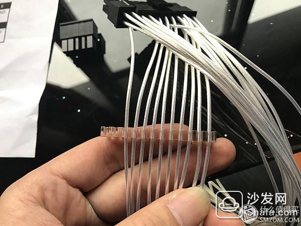
After inserting the 24PIN header of the motherboard, since the other end is 10+18PIN, patients with obsessive-compulsive disorder can distinguish the lines first, as shown below:
Divide the 10PIN and 18PIN lines that need to be inserted.
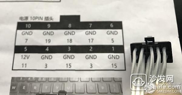
Pay special attention when inserting the terminal. It is very troublesome to insert the wrong back. Be sure to compare the line-sequence diagrams that you made before and insert one by one in the order. We first insert 10PIN this plastic shell, according to the line sequence diagram, 1 plug 15th, 2nd plug 3rd, 3rd plug 15th, 4th plug 3rd, and so on......
All inserted ~
After all the plug-in is finished, check with a multimeter and check the method to see the previous sideline instructions. If there are no multimeters, do a visual inspection.
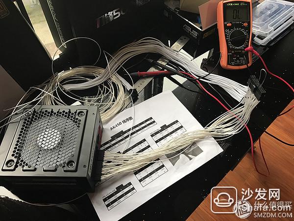
After the inspection, in order to ensure that nothing goes wrong, I started the power supply with no load and tested the voltage of each connection with a multimeter. The method is to use a pin to short the 24PIN header No. 16 and No. 15 or No. 17 (16 is the switch, 15 and 17 are all ground wires), then the power switch is turned on and the power is turned on. Then put the multimeter into the following stalls, black pen ground wire (that is, GND) red pen test the voltage of each interface one by one to see if it is consistent with the ATX power definition, the following specific methods:
First use a pin to short the no-load start power, we see the fan is turning. The power supply has started.
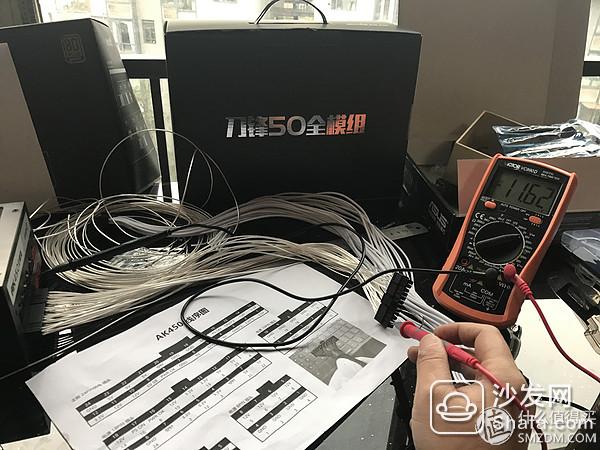
Then debug the multimeter to DC 20V, black pen ground wire, and red pen to test each pin of the 24PIN terminal voltage and ATX power supply. The definition of this interface is 3.3V, the test result is 3.35V, and it is normal within plus or minus 5%.

This interface is -12V, test result - 11.62V, normal.
If there is a mistake, use the withdrawal needle to exit the line and reconnect. The method of exiting the line: Insert the back line against the gaps on both sides of the quasi-power interface, insert it with force, and then the terminal can be pulled out.
After the test, it is successful. The most difficult motherboard 24PIN power supply has been done, the other module line according to their own needs to do the above method. The other lines are up to 8 lines, which is relatively simple.
The whole article is finished~!
KNBL1-32 Residual Current Circuit Breaker With Over Load Protection
KNBL1-32 TWO FUNCTION : MCB AND RCCB FUNCTIONS
leakage breaker is suitable for the leakage protection of the line of AC 50/60Hz, rated voltage single phase 240V, rated current up to 63A. When there is human electricity shock or if the leakage current of the line exceeds the prescribed value, it will automatically cut off the power within 0.1s to protect human safety and prevent the accident due to the current leakage.
leakage breaker can protect against overload and short-circuit. It can be used to protect the line from being overloaded and short-circuited as wellas infrequent changeover of the line in normal situation. It complies with standard of IEC/EN61009-1 and GB16917.1.
KNBL1-32 Residual Current Circuit Breaker,Residual Current Circuit Breaker with Over Load Protection 1p,Residual Current Circuit Breaker with Over Load Protection 2p
Wenzhou Korlen Electric Appliances Co., Ltd. , https://www.zjmannualmotorstarter.com