
Analog video is a mature, reliable technology that can be expanded to meet the requirements of automotive applications. Reasons for continuing to use analog video include: easy access to low-cost circuit design, the ability to use inexpensive copper cables, and the gradual degradation of analog video performance in noisy environments. Today's cars, off-road vehicles and trucks have many improved features, such as looking around cameras, consumer entertainment units and navigation systems, all of which produce analog video content. A typical vehicle with these features is shown in Figure 1.
This article refers to the address: http://
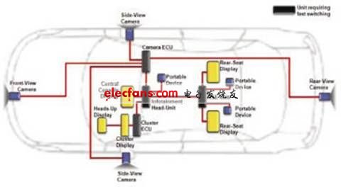
Figure 1 Typical car video system
As the demand for "vehicle video" continues to grow, the rapid switching of analog video in automotive infotainment applications has become a key criterion. Consumers want to seamlessly switch to different analog video sources in the blink of an eye (200ms or less). The fast switching feature is especially important when it is necessary to switch to a video source such as a rear view camera for security reasons. While maintaining high video quality, the requirement to perform fast switching increases the performance standards of the video decoder used in the in-vehicle display unit. In contrast, most video decoder products are designed for the television market, and their key performance criteria are high video quality and robustness to non-standard, poor time-base video signals such as weak RF and VCR sources. These video decoders must maintain a constant output timing even if the input time base has been corrupted. The locking and synchronization requirements for such applications are exactly the opposite of the requirement for fast switching between video sources. This article explores the challenges faced by video designers in implementing fast switching systems and presents practical solutions.
Fast switching challenge
In response to the challenging requirements of non-standard and poor time base sources, the industry has conducted extensive research and design work on the development of video decoders. The fast switching application discussed in this paper presents new challenges. However, when we envision a solution that can be applied to both TV and automotive applications, we found this to be an almost impossible task. These two signal types are mutually exclusive, and design techniques that can better handle one signal type tend to weaken the processing of another signal type, and vice versa. After a long period of effort, ADI's video decoder designers have finally achieved fast switching performance while maintaining compatibility and image quality.
When the input video stream is interrupted, the TV video decoder relies on "inertia" to pass the blackout period like a flywheel, and then regenerates the nominal sync signal when needed. Most decoder algorithms ignore input timing interrupts, as shown in Figure 2. In order to implement a video decoder design that can tolerate video stream interruption without affecting image quality, there are numerous design challenges that need to be overcome.
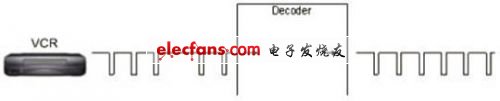
Figure 2 Typical TV video decoder application
In automotive applications, in order to achieve fast switching of analog video, it is necessary to ensure that the video source maintains a constant and correct time base. Synchronously locking video sources is costly, increasing cable cost, board area, and control processing requirements, all of which are key considerations in automotive application design. In principle, high performance video decoders must minimize the total system cost. Figure 3 is a schematic diagram of a typical automotive application requiring fast switching.
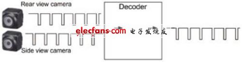
Figure 3 car video decoder application
Choose the right video decoder
When selecting a video decoder for a fast switching application, it is often difficult to determine the fast switching performance of the decoder from the technical specifications section of the data sheet. Automatic detection of switching speed, color lock time, and vertical lock time are all indicators of the fast switching performance of the decoder, but it does not reflect the whole situation. The system designer should ensure that the selected decoder is further optimized for fast switching applications. Some key product features that need to be addressed include the ability to disable Hsync (horizontal synchronization) and Vsync (vertical synchronization) processing modules; the ability to control mandatory application standards, or at least reduce the number of input standards that allow automatic detection; And the control option of the Hsync count in the unlocked state; the timing of the analog input circuit can be forcibly re-acquired; the interrupt can be generated when the decoder is locked or unlocked.
Disable Hsync and Vsync processing modules
The Hsync and Vsync processing modules support high performance decoders that lock bad time base signals. If the input source applied to the decoder has a good time base, the selected decoder should provide control options to disable these modules in order to reduce the lock time of the decoder.
Mandatory application of standards
If the input source standard is known during design, the standard should be locked by the decoder settings, which reduces the lock time because the decoder does not need to spend time performing an automatic detection algorithm to determine the input video standard.
Reduce Hsync count
When selecting a decoder for a fast-switching application, the system designer should ensure that the decoder has programming capabilities that allow the user to reduce the number of consecutive correct Hsync pulses that the video decoder must detect (in order to determine that it has locked the video signal). The Loss of Lock (COL) limit should also be lowered so that the video decoder can determine that it has lost lock and then search for a new input video type by simply losing fewer consecutive Hsync pulses.
Forced reacquisition timing
For fast switching decoder selection, the ability to force a reset of the video decoder front-end analog circuitry is also important, with the goal of reinitializing the module used to lock the video signal. By forcing reacquisition timing, the front-end module resets and searches for video signals, ensuring that new video sources are quickly locked.
Interrupt when the decoder is locked or unlocked
The selected video decoder should have a dedicated interrupt pin that, when the decoder is locked or unlocked, can issue a prompt so that the system controller can respond to these events without continuously monitoring the decoder through I2C. Impact on the output video
Since the video source is not locked in sync, it is not possible to seamlessly switch from one input video to another. The output video stream is affected when the decoder switches from the timing of one input to the video timing of the other input. As shown in FIG. 4, the image during the switching is damaged. This phenomenon cannot be avoided when switching between asynchronous video sources.
Different systems use different solutions to prevent tearing of video images displayed on the screen. The system controller should be able to react quickly to the interrupt generated by the decoder, control the image displayed on the screen during the switch, and ensure that the displayed image does not contain the tear phenomenon shown in Figure 4.

Figure 4 screenshot of the output video switch
Sequence of events during switching
This section describes the sequence of events that occur when you switch to a new input video signal. This will help the system designer to quantitatively evaluate the fast switching performance of the selected video decoder.
Figure 5 shows the sequence of events that occurred after the video signal was acquired. The following describes these events in order:

Figure 5 Input and output video signal waveforms
1. Perform an I2C write operation on the decoder. Set up the decoder, switch to the new video input, and tell the video standard. The write operation to speed up the switchover is performed at this time.
2. The analog clamp circuit responds to the video input. In a typical application, the video signal is capacitively coupled into the video decoder. The decoder must then ensure DC recovery of the video signal and clamp the video blanking level so that the ADC outputs a specific code. There are several ways to do this. The most common method is to provide source current and sink current at the input node of the decoder. Figure 6 is a typical diagram of a video decoder clamped video signal.
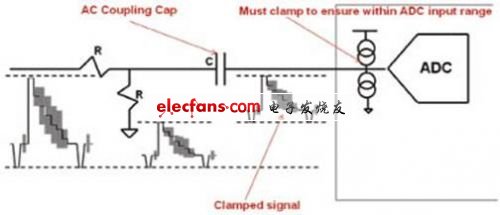
Figure 6 Video signal typical clamp
3. The video is fixed at the correct level and the sync signal is extracted. High-performance video decoder products include both coarse and fine-tuned clamp loops. After the coarse-tuning clamp circuit adjusts the video signal to near the correct voltage, the fine-tuning clamp circuit fully optimizes the video signal level and maintains the video input at this correct DC level. The input video is now fixed at a stable DC level and the blanking level is set to a known ADC code. The decoder extracts the sync signal from the video signal and monitors the Hsync, Vsync, and Field sequences to determine the input video standard. If you use the auto-detect feature, the time to determine the video standard will be extended.
4. The decoder outputs correct and stable video timing. The decoder locks the input video signal, optimizes the internal IP block and filter for that input video type, and begins to output a stable and correct video timing to display the correct video image on the LCD panel or screen.
The above results are all based on measurements performed using ADI decoders such as the ADV7180 and ADV7181C, which meet fast switching requirements.
ADI's decoders are used in the automotive industry to meet the fast switching needs of many automotive system suppliers. The ADV7180 and ADV7181C have all of the fast switching features described in this article.
to sum up
This article explains why analog video is still popular in automotive applications and the advantages of analog video over other solutions. Automakers have seen a feature-rich infotainment system that helps increase sales profits and enhance safety. With the rapid development of the "vehicle video" system, it is likely that a car with five LCD panels will appear in the near future.
The 10KV/11KV medium voltage variable speed drives are mainly used to drive various high-voltage motors, such as power stations, metallurgical industry, petrochemical, cement manufacturing, water supply and sewage treatment, mining, papermaking, etc. FGI`s high voltage drives adopt modular design, multi-stage power unit series technology, with low input harmonic content and high power factor. The Medium Voltage Inverter is small in size, easy to install and debug, and easy to maintain.
10Kv And 11Kv Medium Voltage Drives
Vfd Inverter,High Voltage Inverter,High Voltage Power Inverter,10Kv And 11Kv Medium Voltage Drives,High Watt Voltage Converter,Medium Voltage VFD Specification
SHENZHEN FGI SCIENCE AND TECHNOLOGY CO., LTD , https://www.fgi-tech.com