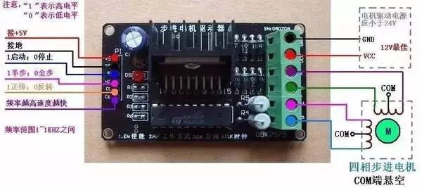
**Wiring Diagram of Mitsubishi PLC and Stepper Motor Driver**
A stepper motor is an actuator that converts electrical pulses into angular displacement. When the stepper driver receives a pulse signal, it drives the motor to rotate in a specific direction by a fixed angle, known as the "step angle." The rotation occurs in discrete steps, allowing precise control over the angular movement. By adjusting the number of control pulses, the position can be accurately controlled. Additionally, the speed and acceleration of the motor can be regulated by changing the frequency of the pulses, making it ideal for speed control applications.
Stepper motors are widely used in open-loop control systems due to their high precision and lack of accumulated error, ensuring 100% accuracy. This makes them suitable for various industrial and automation applications.

**Positioning Principle and Scheme**
When a stepper motor moves an actuator from one position to another, it typically goes through three stages: acceleration, constant speed, and deceleration. If the operating frequency of the motor is lower than its starting frequency, it can be started directly at that frequency and continue running. However, if the frequency is higher, starting directly may cause the motor to lose steps or even stall. Similarly, stopping suddenly at a high frequency can result in overshooting due to inertia, which affects positioning accuracy.
To avoid these issues, the motor must be accelerated and decelerated properly to reach the desired position quickly without losing steps or overshooting. Two common methods for controlling the frequency are linear and exponential curve-based approaches. While exponential methods offer better tracking, they may not be ideal for large speed changes. Linear acceleration, on the other hand, is smoother and easier to implement with software, making it more practical for fast positioning.
**Positioning Plan**
To ensure accuracy while maintaining efficiency, the positioning process is often divided into two stages: coarse and fine positioning. In the coarse stage, a larger pulse equivalent (e.g., 0.1 mm/step) is used to move quickly, while the fine stage uses a smaller pulse equivalent (e.g., 0.01 mm/step) for precise positioning. Since the fine positioning stroke is shorter, the overall speed is not significantly affected.
For example, in a system where the total movement is 200 mm, the first 196 mm can be covered using coarse positioning, and the final 4 mm using fine positioning. This approach allows for faster movement while still achieving accurate results. Mechanical shifting mechanisms can also be used to switch between different pulse equivalents during the process.
**Overview of the Positioning Program Design**
In modern PLCs, such as the Siemens S7-200 series, advanced functions like PTO (Pulse Train Output) and PWM (Pulse Width Modulation) are available. These allow for high-speed pulse generation at up to 20 kHz. In this application, the multi-segment pipeline mode of PTO is used for coarse positioning, while the single-segment mode is used for fine positioning.
Assuming a starting frequency of 2 kHz and a maximum of 10 kHz, the acceleration and deceleration phases are programmed with appropriate pulse increments. For example, during the acceleration phase, the cycle increment is set to -2 ms, and during deceleration, it is set to +1 ms. The envelope table is stored in memory locations starting from VB500, with each segment containing the initial period, increment, and number of pulses.
**Source Code Example**
```assembly
Main Program
LD SM0.1
R Q0.0, 1
CALL 0
LD M0.0
R Q0.0, 1
CALL 1
; Subroutine 0 - Coarse Positioning
LD SM0.0
MOVB 16#A0, SMB67
MOVW 500, SMW168
MOVB 3, VB500
MOVW 500, VW501
MOVW -2, VD503
MOVD 200, VD505
MOVW 100, VW509
MOVW 0, VD511
MOVD 1360, VD513
MOVW 100, VW517
MOVW 1, VD519
MOVD 400, VD521
ATCH 2, 19
ENI
PLS 0
; Subroutine 1 - Fine Positioning
LD SM0.0
MOVB 16#8D, SMB67
MOVW 500, SMW68
MOVD 400, SMD72
ATCH 3, 19
ENI
PLS 0
; Interrupt Program 2
LD SM0.0
M0.0
; Start fine positioning
; Interrupt Program 3
LD SM0.0
M0.1
; Perform additional functions
```
This program ensures smooth and accurate motion control, combining both coarse and fine positioning stages to achieve optimal performance in industrial automation applications.
ftth drop cable,ftth cable,drop cable ftth,optical fiber drop cable,outdoor ftth drop cable
Guangzhou Jiqian Fiber Optic Cable Co.,ltd , https://www.jqopticcable.com
