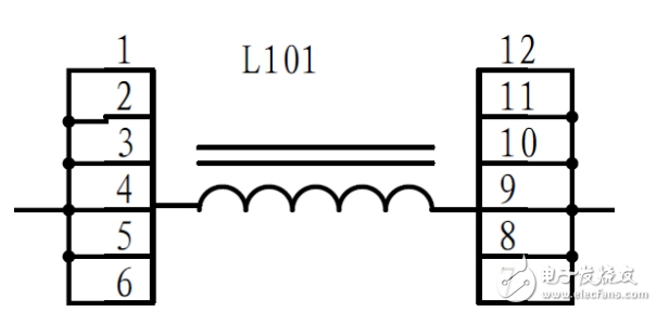
Known Parameters:
Input voltage: 12V Vin
Duty cycle: don
Output voltage: 36V Vout
Output power rating: 150W Pmon
Maximum output power: 200W Pmax
Minimum output power: 50W Pmin
Boost diode voltage drop: 1V Vd
Operating frequency: 100kHz f
Efficiency set to: 88% η
1. Duty Cycle CalculationDuring steady-state operation, the increase in inductor current during the on-time is equal to the decrease during the off-time. This relationship can be expressed as:
(Vi * don) / (f * L) = [(Vout + Vd - Vi) * (1 - don)] / (f * L) (1)
Simplifying this equation gives:
Don = (Vout + Vd - Vi) / (Vout + Vd) (2)
Substituting the known values, we get:
Don ≈ 0.6756756757
We round it to Don = 0.68 for practical purposes.
2. Inductor Value CalculationTo ensure that the inductor current rises to the output current level during each switching cycle, the inductance value is calculated using:
L = (Vin² * don * Vout * η) / [2 * f * Pout * (Vout - Vin * η)] (3)
Where L is in henries (H). When the output power is at its minimum (Pout = 50W), the calculation yields:
L ≈ 12.1938μH
We choose L = 12μH for the design.
The ripple current (dIL) is calculated as:
dIL = Vi * Ton / L
This ripple is set to 20% of the average inductor current (Iin), where:
Iin = Vo * Io / Vi
IL_avg = Iin
IL_peak = 1.1 * Iin
IL_rms = IL_avg * sqrt(1 + (0.22 / 12))
The inductor is chosen such that the ripple current is 20% of the average, which helps in minimizing losses and improving efficiency.
3. Schottky Diode SelectionThe peak current through the diode is:
Id_peak = 1.1 * Iin
The reverse voltage rating of the diode must be at least equal to the output voltage:
Vrd = Vout
This ensures the diode can handle the voltage when the switch is off.
4. Switching Transistor SelectionThe peak current through the switch is:
Isw_peak = 1.1 * Iin
The voltage across the switch during turn-off is:
Vsw = Vout
The transistor must be able to withstand this voltage and handle the peak current.
5. Capacitor SelectionThe RMS ripple current for the input capacitor is:
Icin_rms = dIL / 120.5
The RMS ripple current for the output capacitor is:
Ico_rms = sqrt(Io² * D + (Iin - Io)² * (1 - D))
Capacitors are selected based on their voltage rating, ripple current capability, and capacitance value to ensure stable output performance.
6. Core, Turns, and Air Gap Design1) Using a magnetic core PQ3230 with an effective area (Ae) of 161 mm² and a maximum flux density (Bmax) of 0.23 T,
2) The number of turns (N) is calculated as:
N = (L * Ipmax) / (Bmax * Ae) (4)
Where L is in microhenries, Ae in mm², Bmax in tesla, and Ipmax is the peak current at maximum output power.
3) At maximum power (Pmax), the peak current (Ipmax) is:
Ipmax = (2 * Pout * L * f + Vin² * don * η) / (2 * Vin * f * L * η) (5)
Substituting the values, we find:
Ipmax ≈ 22.34A
4) The inductor current during the on-time (Ion) is given by:
Ion = (2 * Pout - Ip * Vin * η) / (Vin * η) (6)
At Pmin, the calculation confirms that the inductor current matches the output current, validating the previous equations.
5) Using N = 7.5 turns and L = 12μH, the saturation current (Is) of the core is:
Is = (N * Bs * Ae) / L (7)
With Bs = 0.36T at 100°C, we get:
Is ≈ 36.225A
6) The air gap (lg) is calculated using:
lg = 4π * Ae * [(N² / (Lp * 1000)) - 1 / AL] (8)
With AL = 5140 nH/N², the result is:
lg ≈ 0.9mm
7. Wire Diameter Selection1) The maximum RMS inductor current under full load is:
Imax-rms = (Pmax * don) / (Vin * η) + Pmax / Vout (9)
Substituting the values, we get:
Imax-rms ≈ 18.43A
We round it to 18A for practical use.
2) For a current of 18A, the wire diameter is determined using a rule of thumb of 300 mils per ampere, resulting in a cross-sectional area of 3.48 mm².
3) A choice of 110 copper wires with a diameter of 0.2mm is suitable for this application.

Diamond Saw Blade Sharpening Machine
Diamond Saw Blade Sharpening Machine,Grinding Wheel Top Polishing Machine,Diamond Grinding Wheel Sharpening Machine,Diamond Automatic Sharpening Machine
Suzhou Mountain Industrial Control Equipment Co., Ltd , https://www.szmountain.com
