
Circuit Operation Principle The medical ultrasonic atomizer circuit consists of a power supply circuit, a fog level liquid level detection control circuit, an ultrasonic oscillator, and a fan motor M, as shown in Figure 9-111.
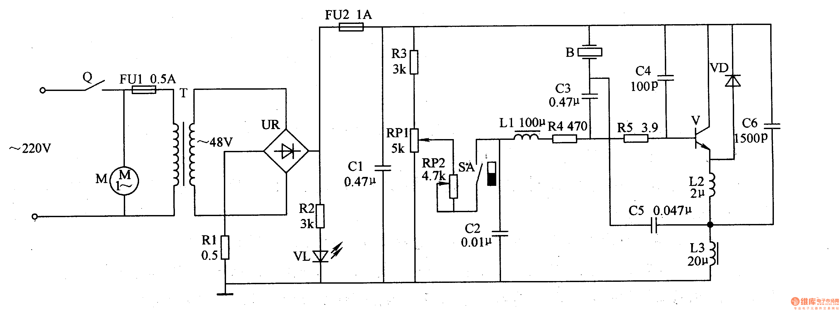
The power circuit is composed of a timer Q, fuses FU1, FU2, a power transformer T, a rectifier bridge stack UR, resistors R1, R2, a light-emitting diode VL, and a filter capacitor Cl.
The fog/level detection control circuit is composed of a resistor R3, a potentiometer RP1, RP2, a magnetically controlled water level switch SA (consisting of a magnetic ring float and a reed switch), and a capacitor C2.
The ultrasonic oscillator consists of a transistor V, resistors R4, R5, capacitors C2-C6, inductors L1-L3, diodes VD and ultrasonic transducers B.
Turn on the timer Q, AC 220V voltage after T step-down, UR rectification, one step through the anal current limiting step-down to VL light; the other way after C2 filtering for the fog amount / water level detection control circuit and ultrasonic oscillator +48V working power supply.
The ultrasonic oscillator is oscillated after being energized to generate an ultrasonic oscillation signal having a frequency of 1.65 MHz or 1.7 MHz, and the drive B generates high-frequency vibration to atomize the liquid. The atomized liquid is blown out from the conduit by the fan.
Adjusting the resistance of RPl can change the level of the base voltage of V, thereby changing the amplitude of the oscillating signal to achieve the purpose of adjusting the amount of fog.
RP2 acts as an auxiliary adjustment (fine tuning).
When the liquid level reaches a certain level in the atomizer, the magnet installed in the float rises as the liquid level rises, the contact of the reed switch SA is turned on, the ultrasonic oscillator works; when the liquid level drops to a certain height When the float is lowered, the contact of the SA is broken, the ultrasonic oscillator stops working, and the liquid level is low and the automatic protection is performed.
Component selection
Both Rl and R3-R5 use a 2W metal film resistor; R2 uses a 1/4W metal film resistor.
Both Cl-C3 and C5 use 1OOV CBB capacitors; C4 and C6 use high-frequency ceramic capacitors.
RPl and RP2 use 2W synthetic carbon film potentiometer or multi-turn wirewound potentiometer, RP2 can also use variable resistor.
VD selects RFl04 type fast recovery diode.
VL selects high brightness LED of φ3mm.
V selects BU406 or SD35 type high back pressure silicon NPN transistor.
Ll selects high frequency choke coil, L2 and L3 select TDK color code inductor.
B selects the finished piezoelectric ultrasonic transducer of 1.65MHz or 1.7MHz.
T selects 40W, the secondary voltage is 45-5OV power transformer.
M selects AC 220V micro fan.
Q selects 0-60min mechanical timer.
3D printing on the pen machine is mainly used in 3 d printing pen, is made from a special custom Dc Gear Motor, mainly used in 3 d printing pen, pen 3 d printing machine has been updated three generations according to the requirements of product.
3D Printing Motor product introduction:
The 3D Printing Motor is based on the deceleration Motor, coupled with supporting gears and ball bearings.The role of the gear reducer is to provide lower speed and greater torque.At the same time, gear box different deceleration ratio can provide different speed and torque.It's mostly rolling.


Features: 3D Printing Motor, small size, large torque, low noise, durable, low energy consumption, customized power design, convenient installation and maintenance;
Simplify design and save space.
Features: usually used financial equipment, office equipment, electronic locks, wireless charger, remote control toys, precision instruments and meters, automobile industry, medical equipment, consumer electronics, household appliances, electric glass doors and Windows, etc., wide application range
Method of use: the best stable in horizontal plane, installed on the 3D Printing Motor output shaft parts, cannot use a hammer to knock, knock prone to press into the 3D Printing Motor drive, may cause damage to internal components, and cannot be used in the case of blocked.


Operating temperature range:
3D Printing Motor should be used at a temperature of -10~60℃.
The figures stated in the catalog specifications are based on use at ordinary room temperature catalog specifications re based on use at ordinary room temperature (approximately20~25℃.
If a 3D Printing Motor is used outside the prescribed temperature range,the grease on the gearhead area will become unable to function normally and the motor will become unable to start.Depending on the temperature conditions ,it may be possible to deal with them by changing the grease of the motor's parts.Please feel free to consult with us about this.
Storage temperature range:
3D Printing Motor should be stored ta a temperature of -15~65℃.
In case of storage outside this range,the grease on the gearhead area will become unable to function normally and the motor will become unable to start.
Service life:
The longevity of 3D Printing Motor is greatly affected by the load conditions , the mode of operation,the environment of use ,etc.Therefore,it is necessary to check the conditions under which the product will actually be used .The following conditions will have a negative effect on longevity.Please consult with us should any of them apply.â—Use with a load that exceeds the rated torque
â—Frequent starting
â—Momentary reversals of turning direction
â—Impact loads
â—Long-term continuous operation
â—Forced turning using the output shaft
â—Use in which the permitted overhang load or the permitted thrust load is exceeded
â—A pulse drive ,e.g.,a short break,counter electromotive force,PWM control
â—Use of a voltage that is nonstandard as regards the rated voltage
â—Use outside the prescribed temperature or relative-humidity range,or in a special environment.
â—Please consult with us about these or any other conditions of use that may apply,so that we can be sure that you select the most appropriate model.
when it come to volume production,we're a major player as well .each month,we rurn out 600000 units,all of which are compliant with the rohs directive.Have any questions or special needed, please contact us, we have the engineer group and best sales department to service to you Looking forward to your inquiry. Welcome to our factory.

3D Printing Motor,3D Printing Gear Motor,3D Printing Pen Motor,3D Printing Spindle Motor
Shenzhen Shunchang Motor Co., LTD. , https://www.scgearmotor.com