
The 555 circuit contains two voltage comparators, a basic RS flip-flop and a discharge switch T. The comparator's reference voltage is provided by a voltage divider consisting of three 5K resistors. They respectively make the non-inverting input of the high-level comparator A1 and the inverting of the low-level comparator A2, and the reference levels of the input terminals are 2/3VCC and 1/3VCC. The outputs of the A2 and A2 control the RS flip-flop state and Discharge tube switch status. When the input signal is from the 6 pin, that is, the high level triggers the input and exceeds the reference level 2/3VCC, the flip-flop resets, the output of the 555 pin 3 outputs a low level, and the discharge switch tube is turned on; when the input signal is from 2 The input of the pin is lower than 1/3VCC, the trigger is reset, the 3 pin of 555 outputs high level, and the discharge switch tube is cut off. RD is the reset terminal (4 pins). When RD=0, 555 outputs a low level. Usually the RD end is open or connected to VCC. 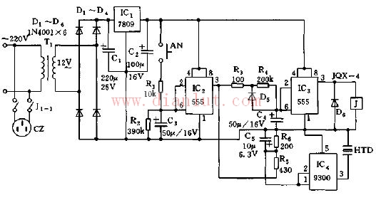
Safety ironing rack circuit diagram
Safety ironing rack circuit diagram
Motorola Mobile Radio,Motorola Walkie Talkie Phone,Motorola Vhf Mobile Radio,Motorola P25 Mobile Radio
Guangzhou Etmy Technology Co., Ltd. , https://www.digitaltalkie.com