
This paper introduces a multi-axis controller based on fpga. The controller is mainly composed of arm7 (LPC2214) and fpga (EP2C5T144C8) and its peripheral circuits, which are used to control the motion of multiple motors at the same time. The Verilog HDL hardware description language is used to implement the motor control logic in fpga, including pulse control signal generation, acceleration and deceleration control, encoder feedback signal discrimination and subdivision, absolute displacement recording, and limit signal protection logic. The paper gives the implementation of some core logic units inside fpga, and uses QuartusII and Modelsim SE software to simulate the key logic and timing. The actual use shows that the controller can well control the motion of the multi-axis motor and achieve high-precision position control.
As motors are widely used in digital control systems, the real-time and accuracy requirements for motor control are increasing. How to control the operation of the motor flexibly and effectively has become the main direction of research. In this paper, Field Programmable Gate Array (fpga) is used to control the motor through Verilog language programming. The use of fpga design has the advantages of hardware design software, high integration, high operating frequency and so on. Fpga's biggest feature is flexibility, to achieve any digital circuit you want to achieve, you can customize a variety of circuits, reduce the constraints imposed by dedicated chips, and truly tailored for your own products. The design can be flexibly changed during the design process, and its powerful logic resources and register resources allow you to easily use the design concept. Parallel execution, hardware implementation can handle a large number of high-speed electronic circuit design requirements in the design.
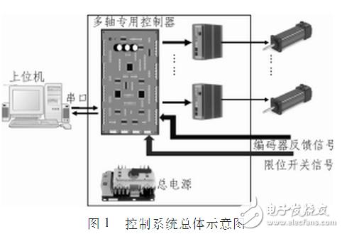
1 Multi-axis controller main functionThe multi-axis controller is used together with the host computer and the motor driver. Figure 1 is a general schematic diagram of a control system composed of a multi-axis controller. The controller receives the control command sent by the host computer, analyzes and processes the corresponding direction signal and pulse signal to the driver, thereby achieving the purpose of controlling the operation of the motor. In order to improve the control precision of the system, the encoder signal of the motor is input as a feedback signal to the controller (internal automatic discrimination and four subdivisions). During the movement of each axis, the dedicated controller records the absolute displacement of the motor running, and can upload the absolute position information of each axis to the upper computer in real time. In addition, in the process of motor operation, in order to ensure the safety of motor operation, the controller also uses limit signal feedback to achieve full hardware protection measures.
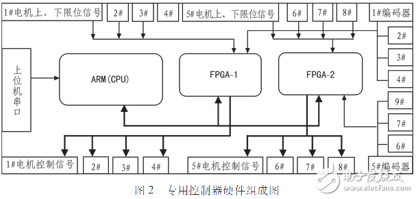
The dedicated controller consists of arm (LPC2214), fpga (EP2C5T144C8), driver interface circuit, encoder interface circuit, limit detection circuit and power supply circuit. Figure 2 shows the hardware composition of an eight-axis motor controller. The arm realizes communication with the host computer through the serial port, parses the control command obtained from the host computer, and generates corresponding output signals to the driver interface through the fpga, and the driver interface is externally connected to the driver. The encoder signal is connected to the encoder interface as a position feedback signal to form position loop feedback. The limit signal is connected to the limit detection interface as a safety detection signal, which adds a safety guarantee to the entire system.
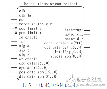
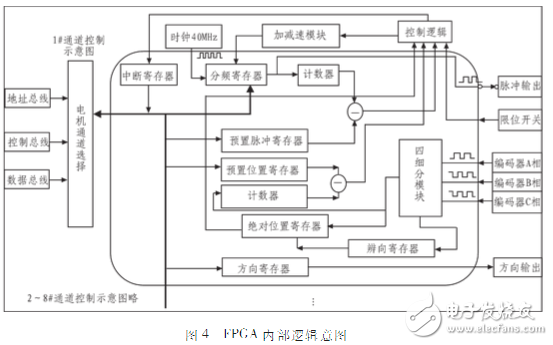
In the process of completing the whole control, the arm is only responsible for the tasks of command parsing, control command sending, real-time data uploading, etc. fpga is the core of the multi-axis dedicated controller. Through the Verilog HDL language, the acceleration and deceleration curve, encoder signal direction and four subdivisions, absolute displacement recording and other functions are realized inside fpga. Figure 3 is the overall input and output signal diagram of the motor control. The motor channel selection is performed by the chip select signal CS, the read valid signal rd_enable, and the write valid map signal wr_enable. Figure 4 shows the internal logic diagram of fpga for 1# channel control. The main modules will be described in detail below.
1) Acceleration and deceleration curve module
In order to control the operation of the motor more effectively and ideally, an acceleration/deceleration curve module is designed inside the fpga. In this paper, a method of approximating the exponential acceleration/deceleration curve is adopted. As shown in Fig. 5, the approximate exponential acceleration curve is obtained, and the deceleration curve is symmetric with it. The velocity is equidistantly distributed, so the time held at this speed level is not the same as the field. For the sake of simplicity, the product of the speed series N and a constant C is used to simulate and hold the time instead of being cooked. Therefore, for every level of speed, the motor must go to the NC step at this speed level (where N is the speed level).
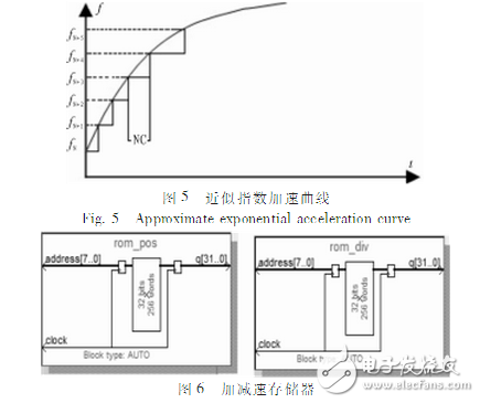
Two ROM modules named rom_pos and rom_div are created. As shown in FIG. 6, rom_pos is a pulse number memory, and rom_div is a frequency division value memory. The two memories are connected by the same address line so that one address corresponds to a set of pulse numbers and frequency division values.
After fpga obtains the direction signal, pulse (distance) signal, and target frequency division value, if the motor does not need acceleration and deceleration during operation, the target frequency division value can be directly controlled to transmit the pulse signal. If acceleration/deceleration is required, the acceleration/deceleration module is called inside fpga. Obtain a set of data according to the address line, that is, the number of pulses pul_cnt and the frequency division value div_num, send pul_cnt pulses with the frequency division value of div_num size, and then send pulses according to the next set of data values ​​until the frequency division value reaches the target frequency division. The deceleration process is symmetric with the acceleration process up to the value. When the motor runs to half the stroke according to the pulse (distance) signal, if the frequency division value has not reached the target frequency division value, forced deceleration is performed at this time.
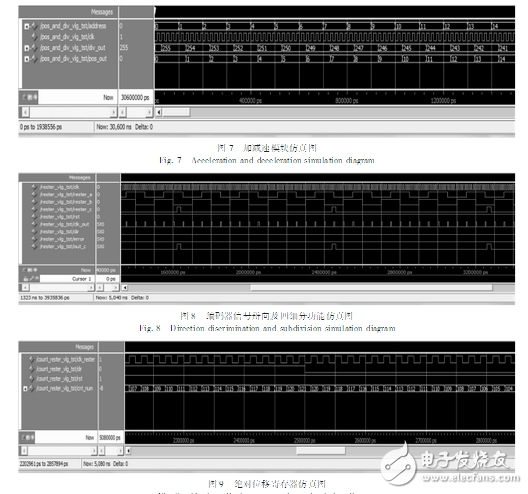
Write the emulation program so that the two memory address lines are the same, and the memory address address is incremented by one, so that the data of the memory cells corresponding to the two memories can be read at one time. The function simulation of the acceleration/deceleration module is performed by using the Modulesim simulation tool. The simulation result is shown in Figure 7. Accessing a memory address corresponds to the output of a set of pulse numbers and frequency division values.
2) Encoder feedback discrimination and four subdivisions
The encoder feedback signal consists of three-phase signals A, B, and Z. The phase signals of A and B are 90 degrees out of phase, and there are four different combined states of A and B phase signals in one cycle. According to this feature, the encoder signal can be deciphered and subdivided. The Z-phase signal is the encoder zero signal. When the encoder rotates one turn, the Z-phase will have a signal output.
After successful compilation in the Quartus II compiler environment, the Modulesim simulation software is called to write a simulation program to generate a global clock, a reset signal, A, B phase signals and Z phase signals with a phase difference of 90 degrees. As shown in Fig. 8, the function simulation diagram of the encoder signal phase and the four subdivisions used in the multi-axis controller is given.
3) Absolute displacement record
The multi-axis dedicated controller can upload the absolute displacement of the motor running to the host computer in real time. The realization of this function depends on the logic function of the absolute displacement recording part in fpga. An absolute shift register is set inside fpga to count the encoder feedback signal (after discriminating four subdivisions). When a pulse of the encoder signal arrives, different arithmetic processing is performed according to the backward direction signal. If the direction is positive, the value of the absolute shift register is incremented by one, otherwise the minus one is performed to achieve the purpose of recording the absolute displacement. And the arm can read the value of the absolute displacement register at any time, and then upload the value to the upper computer, thereby completing the function of uploading the running position information of the motor in real time. Write the simulation program to simulate the function of the absolute shift register. The result is shown in Figure 9.
4 ConclusionThe scheme has been successfully applied to the motion control of a 6-axis Stewart platform. At the same time, the motion positioning accuracy of 0.1μm is achieved, and the motion mechanism is well protected. In many experiments and practical use, the dedicated controller runs safely. reliable.
Imd Products,Camber Imd Panel Products,Air Conditioner Imd Panel Products,Imd Panel Products With Button
Dongguan Nanhuang Industry Co., Ltd , https://www.soushine-nanhuang.com