
Many people think that DIY speakers are simpler than pre-stage, post-stage and DAC, because it is just a wooden box with crossover and unit. There is really no technology at all. Of course, it's really easy to make a sound, but it's a little difficult to make a good sound.
The design of crossovers and speakers has always been regarded as a secret collection by manufacturers. This makes it a pity that only a few DIYers can implement speakers. I try to unlock this secret for everyone here, I hope you can have a preliminary understanding of the design after reading this article, and then you can make your first pair of speakers.
I would also like to thank Brother Limin for the opportunity to write this article.
There will be three modules in this article:
Crossover articles speaker articles practical articles
Introduction
First of all, I want to give you an explanation. I have a preliminary understanding of the various parts of the speaker:
Super Treble: Responsible for frequencies above 22kHz
Treble: Responsible for 5000Hz ~ 22kHz frequency.
Alto: responsible for 1500 ~ 5000Hz frequency
Bass: Responsible for frequencies below 1500Hz
Subwoofer (increasing) is responsible for frequencies below 200Hz
Crossover: The specified frequency is assigned to each unit to work.
Speaker: divided into sealed, inverted and labyrinth
The structure of the speaker unit is not explained here, because it is too complicated to explain clearly, and I will use space to explain later.
Crossover
On the surface, the crossover is just a very simple circuit, and it should not be too difficult to design. But in reality it is completely different. The measurement, analysis, and required equipment contained in it are indeed quite complicated.
But this time I ’m going to talk about not such a deep and difficult measurement ... but to start from the most basic, so that there is a complete concept. Dividers can be divided into the following two categories:
Active splitting and passive splitting: The difference between the two is very large. Active splitting is used between the pre-stage and the post-stage. Using OPA to achieve the purpose of voicing requires multiple post-stages. The passive crossover (hereinafter referred to as the crossover) is the crossover placed in the speaker, and the inductive parts are used to achieve the purpose of dividing the sound. But only one post-level can be used. Also introduced this time.
Editor's note: Active crossover, also known as active crossover (Hong Kong terms), AcTIve Cross Over; Passive crossover, also known as passive crossover (Hong Kong terms), Passive Cross Over. Among them, the crossover can be further divided into:
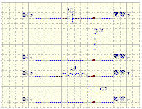
The two-way design includes:
First-Order route map
C1 = 0.159 / RH F L1 = RL / 6.28 F
In the formula:
RH = treble impedance value
RL = bass impedance value
F = crossover point
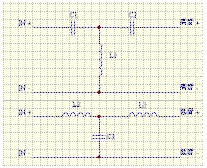
Second-Order Roadmap
Second-Order Linkwitz-Riley
C1 = 0.0796 / RH F L1 = 0.3183 RL / F
C2 = 0.0796 / RF F L2 = 0.3183 RH / F
Second-Order Bessel,
C1 = 0.912 / RH F L1 = 0.2756 RL / F
C2 = 0.0912 / RL F L2 = 0.2856 RH / F
Second-Order Butterworth
C1 = 0.1125 / RH F L1 = 0.2251 RL / F
C2 = 0.1125 / RL F L2 = 0.2251 RH / F
Second-Order Chebychev
C1 = 0.1592 / RH F L1 = 0.1592 RL / F
C2 = 0.1592 / RL F L2 = 0.1592 RH / F
In the formula:
RH = treble impedance value
RL = bass impedance value
F = crossover point
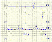
Third-Order Roadmap
Third-Order Butterworth
C1 = 0.1061 / RH F L1 = 0.1194 RH / F
C2 = 0.3183 / RH F L2 = 0.2387 RL / F
C3 = 0.212 / RL F L3 = 0.796 RL / F
In the formula:
RH = treble impedance value
RL = bass impedance value
F = crossover point
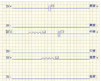
Fourth-Order Route Map
Fourth-Order Linkwitz-Riley
C1 = 0.0844 / RH F L1 = 0.1000 RH / F
C2 = 0.1688 / RH F L2 = 0.4501 RH / F
C3 = 0.2533 / RL F L3 = 0.3000 RL / F
C4 = 0.0563 / RL F L4 = 0.1500 RL / F
Fourth-Order Bessel
C1 = 0.070 / RH F L1 = 0.0862 RH / F
C2 = 0.0719 / RH F L2 = 0.4983 RH / F
C3 = 0.2336 / RL F L3 = 0.3583RL / F
C4 = 0.0504 / RL F L4 = 0.1463 RL / F
Fourth-Order Butterworth
C1 = 0.1040 / RH F L1 = 0.1009 RH / F
C2 = 0.1470 / RH F L2 = 0.4159 RH / F
C3 = 0.2509 / RL F L3 = 0.2437 RL / F
C4 = 0.0609 / RL F L4 = 0.1723 RL / F
Fourth-Order Legendre
C1 = 0.1104 / RH F L1 = 0.1073 RH / F
C2 = 0.1246 / RH F L2 = 0.2783 RH / F
C3 = 0.2365 / RL F L3 = 0.2294 RL / F
C4 = 0.091 / RL F L4 = 0.2034 RL / F
Fourth-Order Gaussian
C1 = 0.0767 / RH F L1 = 0.1116 RH / F
C2 = 0.1491 / RH F L2 = 0.3251 RH / F
C3 = .2235 / RH F L3 = 0.3253 RL / F
C4 = 0.0768 / RL F L4 = 0.1674 RL / F
Fourth-Order Linear-Phase
C1 = 0.0741 / RH F L1 = 0.1079 RH / F
C2 = 0.1524 / RH F L2 = 0.3853 RH / F
C3 = 0.2255 / RL F L3 = 0.3285 RL / F
C4 = 0.0632 / RL F L4 = 0.1578 RL / F
The three-way design includes:
First-Order route map
First-Order (I) Alto is connected
[page_break]
C1 = 0.1590 / RH FH L1 = 0.0458 RM / FM
C2 = 0.5540 / RM FM L2 = 0.1592 RL / FL
First-Order (II) Alto is connected
C1 = 0.1590 / RH FH L1 = 0.0500 RM / FM
C2 = 0.5070 / RM FM L2 = 0.1592 RL / FL
Second -Order route map
Second -Order (I) midrange gain 2.08dB midrange reverse connection
C1 = 0.0791 / RH FH L1 = 0.3202 RH / FH
C2 = 0.3236 / RM FM L2 = 1.0291 RM / FM
C3 = 0.0227 / RM FM L3 = 0.0837 RM / FM
C4 = 0.0791 / RL FL L4 = 0.3202 RL / FL
Second -Order (II) midrange gain 2.45dB midrange reverse connection
C1 = 0.78 / RH FH L1 = 0.3217 RH / FH
C2 = 0.3046 / RM FM L2 = 0.9320 RM / FM
C3 = 0.0248 / RM FM L3 = 0.0913 RM / FM
C4 = 0.0788 / RL FL L4 = 0.3217 RL / FL
Third -Order (I) Alto gain 1.6dB Alto positive connection
C1 = 0.0995 / RH FH L1 = 0.1191 RH / FH
C2 = 0.3402 / RH FH L2 = 0.0665 RM / FH
C3 = 0.0683 / RM FM L3 = 0.0233 RM / FM
C4 = 0.3125 / RM FM L4 = 0.4285 RM / FM
C5 = 148 / RM FM L5 = 0.2546 RL / FM
C6 = 0.2126 / RL FL L6 = 0.0745 RL / FL
Third -Order (II) midrange gain 2.1dB midrange positive connection
C1 = 0.0980 / RH FH L1 = 0.1190 RH / FH
C2 = 0.3459 / RH FH L2 = 0.0711 RM / FM
C3 = 0.0768 / RM FH L3 = 0.1254 RM / FM
C4 = 0.2793 / RM FM L4 = 0.3951 RM / FM
C5 = 1.061 / RM FM L5 = 0.2586 RL / FL
C6 = 0.2129 / RL FL L6 = 0.0732 RL / FL
Third -Order (III) midrange gain 0.85dB midrange reverse connection
C1 = 0.1138 / RH FH L1 = 0.1191 RH / FH
C2 = 0.2976 / RH FH L2 = 0.0598 RM / FM
C3 = 0.0765 / RM FM L3 = 0.0253 RM / FM
C4 = 0.3475 / RM / FM L4 = 0.3789 RM / FM
C5 = 1.068 / RM FM L5 = 0.2227 RL / FL
C6 = 0.2127 / RL FL L6 = 0.0852 RL / FL
Third -Order (IV) midrange gain 0.99dB midrange reverse connection
C1 = 0.1158 / RH FH L1 = 0.1189 RH / FH
C2 = 0.2927 / RH FH L2 = 0.0634 RM / FM
C3 = 0.0844 / RM FM L3 = 0.0284 RM / FM
C4 = 0.3112 / RM FM L4 = 0.3395 RM / FM
C5 = 0.9667 / RM FM L5 = 0.2187 RL / FL
C6 = 0.2130 / RL FL L6 = 0.0866 RL / FL
Fourth-Order Route Map
Fourth-Order (I) Alto gain 2.28dB Alto positive connection
C1 = 0.0848 / RH FH L1 = 0.1004 RH / FH
C2 = 0.1686 / RH FH L2 = 0.4469 RM / FH
C3 = 0.3843 / RM FM L3 = 0.2617 RM / FM
C4 = 0.5834 / RM FM L4 = 1.423 RM / FM
C5 = 0.0728 / RM FM L5 = 0.0939 RM / FM
C6 = 0.0162 / RM FM L6 = 0.0445 RM / FM
C7 = 0.2523 / RL FL L7 = 0.2987 RL / FL
C8 = 0.0567 / RL FL L8 = 0.1502 RL / FL
Fourth-Order (II) Alto Gain 2.84dB
C1 = 0.0849 / RH FH L1 = 0.1007 RH / FH
C2 = 0.1685 / RH FH L2 = 0.4450 RH / FH
C3 = 0.3774 / RM FM L3 = 0.2224 RM / FM
C4 = 0.5332 / RM FM L4 = 1.273 RM / FM
C5 = 0.0799 / RM FM L5 = 0.1040 RM / FM
C6 = 0.0178 / RM FM L6 = 0.0490 RM / FM
C7 = 0.2515 / RL FL L7 = 0.2983 RL / FL
C8 = 0.0569 / RL FL L8 = 0.1503 RL / FL
Is it complicated? Don't be afraid to just give a few examples, not all of them are actually used. Moreover, it is now possible to use computer programs to calculate. So do n’t worry. In addition to the crossover circuit, the following circuits need to be added to make the effect of the crossover more perfect:
Circuit diagram for reducing treble sensitivity
Generally, the inspiration of treble will be a few dB higher than that of bass, so this circuit should be used to balance the sensitivity of high and low bass.
Editor's note: When using this attenuation network, remember the following points
How many dB are you going to attenuate to match? Note that in terms of voltage gain N times, the formula expressed in dB is
20LOG N. Assuming that the attenuation is ten times, the attenuation is 20LOG10 = 20dB. Conversely, if you plan to attenuate 6dB, it will be one-half the attenuation (20LOG0.5 = -6dB)
The total impedance before and after the attenuation network is added: suppose we originally designed the crossover network with
Impedance RL is assumed, then the impedance after adding two resistors:
R1 + (R2 // RL) = RL, where R2 // RL is expressed as two resistors connected in parallel, and the resultant impedance is 1 / (1 / R2 + 1 / RL)
Circuit diagram of treble impedance compensation
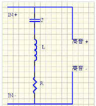
Treble impedance compensation circuit:
We know that the impedance of the unit is not a straight line but a curve, so we have to try to draw this curve to a flat point.
C = 0.1592 / (RE Qes fs)
L = 0.1592 (Qes RE) / fs
R = RE + (Qes RE) / Qms
In the formula: RE, Qes, Qms, fs can be found in the data of the unit.
The answer can be found as long as it is substituted.
The impedance of many trebles is now very straight, so this circuit can also be used.
Bass impedance compensation circuit: Bass impedance compensation circuit diagram
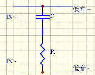
It has been mentioned above that the impedance of the unit is not a straight line, and the impedance curve of the bass is even more ugly. On the impedance curve of the bass, we can see that the impedance values ​​at the low and middle frequency bands have risen above 30 Ohm. It is difficult to pull the impedance of the low frequency band straight, so it is generally ignored , We mainly make the impedance of the mid-band flat.
R = 1.25 RE
C = Le / R2
In
RE = woofer DC resistance value
Le = inductance value of the woofer
[page_break]
Frequency response compensation circuit: Frequency response compensation circuit diagram A
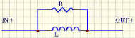
These two circuits have two roles respectively.
The circuit increases the frequency response (larger) and increases the sensitivity.
The circuit increases the frequency response (larger) and lowers the sensitivity.
Frequency response compensation circuit diagram B
L = 0.15916 / f
C = 0.15916 / f
Where f = the minimum value of the frequency response and the calculation of R is difficult to scale. We can try it slowly with 10 ~ 30 Ohm resistance. Try until you think it's better.
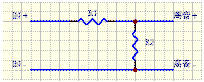
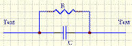
Parallel frequency notch circuit: Parallel frequency notch circuit diagram
The function of this circuit is to reduce a certain frequency band (f1 ~ f2) that protrudes, so that the frequency response is relatively straight.
C = 0.03003 / f
L = 0.02252 / f2 C
R = 1 / 6.2832 CB
In the formula:
f = median of a band to be attenuated
g
(f1 = 2000Hz, f2 = 3000Hz. f = 2500Hz)
C = f1 ~ f2 requires attenuation sensitivity.
Most of the public or methods mentioned above can solve the general design and use. The most important thing is to do more implementation to understand the purpose. We may use the above formula to get very beautiful values, but in actual use (listening) At that time, we have to make some details based on experience.
The introduction of the crossover is over.
If there is any error, please point out the correction.
Reference data: The Loud Speaker Design Cookbook (Fourth EdiTIon)
Speaker articles
The design of the speaker is more complicated than the design of the crossover. The parameters of the instrument used to test ... more. Don't underestimate this box, it is often the key to the entire system. It is difficult to design a good box, I try to explain.
The design of the speaker can be divided into three categories:
Sealed
Reflective
Labyrinth
This time we will introduce two types of sealed and reflective. Because the labyrinth design is very complicated, we are also very difficult to manufacture.
Sealed
Sealed means that the unit is installed in a sealed box to work. The design is simpler than the reflection type. As long as a few formulas can be obtained.
Qr = Qtc / Qts
Vr = Qr ^ 2-1
Vb = Vas / Vr
Qtc, Qts, Vas in the formula are the parameters of the speaker. Vb is the volume of the speaker. (L). But after the calculation, the volume of the unit and the crossover must be added to the final speaker volume. Finally, the damper must be filled into the box, but do not put it too hard. Different dampers will have different tones, for example, the sound of wool is thicker, the tone of warm glass fiber is thinner than wool, and the tone is bright. I think the sound of wave cotton is the worst. My favorite is the cotton in the outerwear I wear in winter. The reaction is quick and clear!
Reflective
Although the design is more complicated than the sealed type, it is not too difficult.
Vb = 20 * Qts ^ 3.3 Vas
Fb = (Vas / Vb) ^ 0.44 * Fs
In the formula: Qtc, Qts, Vas are the parameters of the speaker. Vb is the volume of the speaker (L)
Inverter design
Lv = (23562.5 * Dv ^ 2 * Np / (Fb ^ 2 * Vb))-(k-Dv)
In the formula:
Dv = Diameter of the inverter tube (cm)
Fb = frequency (Hz)
Lv = length of the inverter tube (cm)
Vb = speaker volume (L)
Np = number of inverter tubes
k = final correction value (usually 0.732)
There are many ways to calculate the volume of the speaker, but only one of them. I emphasize that this is just a method, and there may be some discrepancies in practice. I give an example: most of the PRO XX bookshelf models on the market have the same volume. In terms of data, the volume calculated by the different types of woofer units he uses It should be different, but he uses speakers of almost the same volume to install different units. Another example: the same unit is installed in a bookshelf box in factory A, but is already installed in a floor box in factory B. However, it is completely different on the crossover. I think you already understand what I want to say.
The following software can help us design.
FILTER 15
PXOVER
In addition to software, we can use some test hardware to make many different measurements on the computer.
AUDIOMATICA SRL (http: //TIca/clioeng.htm)
You can also find more software at the following website
The Subwoofer Diy Page (http://205.214.207.99/audiodiy/sld/sealed4.htm)
The design of the speaker is the beginning.
Reference data:
The Loud Speaker Design Cookbook (Fourth Edition)
The Subwoofer Diy Page (http://205.214.207.99/audiodiy/sld/sealed4.htm)
The speaker Buliding page (http: //)
Practical article
Everyone has learned the basics of design. It is time to do some homework. In the practical article, I will use some KIT as an internship blueprint, and then improve it. (Note: I do n’t think there is a problem / bad design of the original factory, please do n’t misunderstand.)
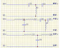
Original crossover circuit diagram
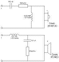
This time I will introduce to you the SEAS EMBLA KIT which is of course the unit used in SEAS. The units he uses are:
Treble --- 25 TAF C / D (H417) metal film treble
Bass --- P17REX (H416) Plastic Bass Bass
How can we see how to change the wiring diagram so well! This time we have to change not only the wiring, but also the treble and bass. We only use KIT speaker design. Why only use original speaker design? As explained in the previous article. The goal is to use no more than HK $ 3000 to complete this implementation. After various changes, this is no longer like EMBLA. So it was renamed SPEAKER ONE. The following is the unit used by SPEAKER ONE:
Treble: 25 TFF (H519) silk film treble
Bass: CC17RCY (H624) Bass Bass
Why do you want to switch to these two units, I think everyone understands at a glance.
The silk film treble is transparent, detailed and analytical.
The bass of the paper cone is sweet and dynamic.
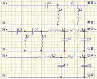
But the most important thing is that the price is cheap, and the saved money can also buy a good in-box wiring. SPEAKER ONE's crossover design is designed using Two ways Second-Order Butterworth.
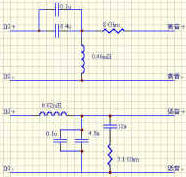
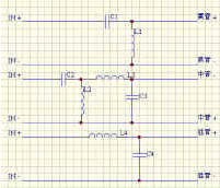
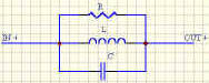
SPEAKER ONE crossover circuit diagram
Although the new crossover is more complicated than the original one, it is really just a few more parts. The coil in the crossover is preferably an air core. 6.4u, 4.8u can use two to three capacitors and come out and then add 0.1u capacitors. As for which brand to use, it depends on your favorite voice. For 8Ω and 7.1Ω resistors, use 5W or more. Among them, the 8Ω resistor is used to attenuate the sensitivity of the treble. The use of 8Ω here may be a bit larger. If you feel that the high tone is dark, you can use it thinner until it is balanced. If you like two-line crossover, you can separate the high and low IN + IN-as shown in the picture. If you don't like it, you can connect the high and low IN + IN-separately. The sound-absorbing material in the box uses my favorite (cotton in the coat). If you can't find it, you can use glass wool instead, but be careful when using it, because the glass wool will make the skin sensitive. The speaker can be found on behalf of the manufacturer.It is best to use 35mm MDF as the material.
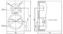
The size in the picture is using 19mm MDF. If you use 35mm MDF, you need to increase the size of H, W, D. The reflection tube can use PVC water pipe. When making the box, ask the teacher to install PVC into the back plate of the box. The length is 12cm longer than the original one, please pay attention here. After many days of production, you can finally listen to it. Do n’t expect the sound to come out very well, because the units, parts, and wiring used are all new. It takes a while for run -in to enter the state. Although the sound of this pair of speakers will not have incomparable analytical power, majestic low frequency, crystal clear high-pitched sound, but the sound coming out is natural, bright and reasonable, the sound field is a pair of very good speakers. The most important thing is that this pair of speakers can be done for only about HK $ 2500. Such a speaker already has such a sound, which is very rare.
Bass: H624 x 2 HK $ 920
Treble: H519 x 2 HK $ 380
Speaker: 1 pair HK $ 800
Crossover, terminal, wiring HK $ 400
TOTAL HK $ 2500
Experience
This is my first pair of speakers and my favorite pair of speakers. There is nothing particularly difficult in manufacturing, but it should be noted that the coil of the crossover should not be too close to the speaker unit, and the placement of the coil should also be careful. It is best to place it horizontally and vertically. Initially, the crossover may not be placed temporarily Put it in the box after slowly listening and fine-tuning. This will save a lot of time.
Small computer system interface (SCSI) is an independent processor standard for system level interfaces between computers and intelligent devices (hard disks, floppy drives, optical drives, printers, scanners, etc.). SCSI is an intelligent universal interface standard.
Plastic SCSI Cover
ShenZhen Antenk Electronics Co,Ltd , https://www.antenk.com