
Design of wireless VoIP system based on ADM5120
VoIP (Voice over IP), because it implements voice communication in IP networks, promotes the use of network resources, reduces the cost of voice services, and has been rapidly developed worldwide. 802.11 wireless local area network (WLAN) frees users from wired network connections. After deploying a WLAN network in an enterprise, the establishment of VoIP applications does not require the transformation of the existing network to meet the needs of voice communication within the enterprise, and to meet the next generation mobile communication applications for data, voice, The development direction of multimedia transmission. This article combines VoIP and WLAN (Wireless LAN), and implements the function of making IP calls in a wireless local area network on the processor ADM5120 of MIPS (Microprocessor without Interlocked Pipeline Stages) architecture. The system communicates in the form of a terminal and is highly mobile.
1 Design of system hardware
1.1 The overall architecture of the hardware
The overall architecture design of the system hardware is shown in Figure 1. The system hardware is mainly composed of five parts: ADM5120 main processor part, call control part, wireless daughter card part, storage part and peripheral connection part. The call control part adopts Infineon's voice chip VINETIC-2CPE, Version 2.1 (PEB3322) as a sub-processor, external user interface circuit SLIC-DC PEB4268 with A / D, D / A conversion function, and a real-time voice processing skeleton together with the storage part ; The wireless daughter card part adopts Atheros WMIA-165G 802.11g Mini PCI module, and uses Madwifi to drive the wireless daughter card; the storage part uses 2 SDRAM memories and 1 NOR FLASH memory; the peripheral connection part includes a WAN port and four LAN port, Mini-PCI interface, RJ-11 interface for outputting analog telephone signals, and RS 232 serial port for debugging. 
1.2 ADM5120 main processor
ADM5120 of Infineon Company of Germany is an embedded processor based on Harvard Architecture SoC (System on Chip). It has a 5-stage pipeline and uses a 32-bit MIPS instruction set. At the same time, ADM5120 is also a typical register-type microprocessor, which is equipped with 32 general registers and a pair of registers Hi and Lo that store 64-bit data and abnormal PC registers. The Hi and Lo registers are used to store the results of fixed-point multiplication. ADM5120 also built-in 32 / 16-bit MIPS32 4KEC processor, which uses TLB (TranslaTIonLookaside Buffer) to achieve memory management and exception handling functions in the pipeline, and uses von Neumann structure to transfer data between memory and registers, Improve the data transmission efficiency and speed up the execution speed of the program. In addition, ADM5120 also integrates a variety of peripheral components, mainly including: PCI (Peripheral Component Interconnect) bus interface, five 100 Mb / s Ethernet interfaces, and also equipped with ADM5120 built-in PHY chip, embedded 16 MB / 85 MHz SDRAM memory provides great convenience for system design.
In this system, the microcontroller interface (non-buffered interface) is connected in parallel with VINETIC, FALSH-RAM, and SDRAM, and the bus widths of 8 B, 16 B, and 32 B are used respectively. The ADM5120 controls the VINETIC connected to it through the microcontroller interface and transmits voice data from the WLAN interface to VINETIC, and vice versa. The general-purpose input / output ports GPIOs of the ADM5120 control the reset signal of VINETIC and generate a chip select signal for VINETIC. At the same time, GPIOs also serve as inputs for VINETIC preparation functions and interrupt signals. The LED indicator connected to the ADM5120 shows the connection status of the WAN and LAN ports and the analog line status of the analog output interface.
1.3 VINETIC voice module
VINETIC (Voice and Internet Enhance Telephony Interface Circuit) is a voice processing module of Infineon, which integrates the codec and voice processing functions to achieve the same voice quality as traditional voice services. VINETIC processes analog telephone signals, voice compression packets, and provides buffering of real-time compression packets. It has functions such as adaptive echo cancellation, mute detection, DTMF signal generation, and decoding.
The main interface circuit of VINETIC chip is shown in Figure 2. Among them, 4 and 5 are chip select input terminals; AD0 ~ AD7: bidirectional input / output signals, the corresponding pins have 3 operating states: low level, high level or high impedance, when CSQ is high level, DOUT It is in a high-impedance state, which requires an external 10 kΩ pull-up resistor; 28 and 29 output digital level, open drain, the corresponding pin has two operating states: active low or tri-state, and allows multiple Device sharing is wired or. Chip power supply circuit part: 66 external phase-locked loop, this phase-locked loop affects the overall performance of the chip, so special attention should be paid to the filter that supplies power to the phase-locked loop; 64 ground the phase-locked loop. 
1.4 Storage module
The system memory module includes 1 NOR FLASH chip MX29LV320 and 2 SDRAM chips W986432DH. The pin layout of MX29LV320 is shown in Figure 3. 
Among them A0 ~ A20: address input; DQ0 ~ DQ14: data input / output; DQ15 / A-1: ​​DQ15 (data input / output in word mode), A-1 (least significant bit address input in byte mode) ); CE: slice start input; WE: write start input; OE: output start input; RESET: hardware restart pin, active low; RY / BY: read / busy output, connected to the main processor ADM5120 RDY lead Feet to increase speed.
The pin layout of W986432DH is shown in Figure 4. Among them A0 ~ A10: address pins; BS0 and BS1: memory bank selection; DQ0 ~ DQ31: data input / output multiplexing pins; RAS: row address strobe; CAS: column address strobe; WE: write allowed , Command input, when sampling at the rising edge of the RAS clock, CAS and WE determine the operation will be performed; DQM0 ~ DQM3: input / output mask, the output buffer is placed in high impedance (2) Delay), and sampling in the write cycle will prevent the write operation with zero delay; CLK: sample input at the rising edge of the clock; CKE: clock start, when CKE is low, enter power-down mode, pause mode or self-charge mode .
2 Design and implementation of system software
The overall architecture of the system software design is shown in Figure 5, which implements UDP-based point-to-point communication and broadcast communication based on ADM5120 in a wireless local area network. UDP (User Datagram Protocol) is mainly used to support network applications that need to transfer data between computers. Many client / server mode network applications, such as network video conference systems, need to use UDP protocol. The UDP protocol is directly on top of the IP (Internet Protocol) protocol and belongs to the transport layer protocol in the network protocol. Because the UDP protocol does not need to establish a connection, it has the advantages of high efficiency, fast speed and less resource consumption. It can be used in message communication and real-time systems to improve the efficiency of data transmission in the system. UDP has multicast and broadcast functions and is an ideal protocol for distributing information. This system also transplants an embedded Web server boa based on ADM5120, which realizes the Web configuration based on B / S mode for VoIP system. 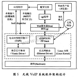
2.1 Implementation of point-to-point communication
In this system, full-duplex communication can be performed between any two applications in a network segment, and each application can be used as both a server and a client. The UDP programming steps are shown in Figure 6. The following is the specific implementation process of peer-to-peer communication between the two applications A and B: 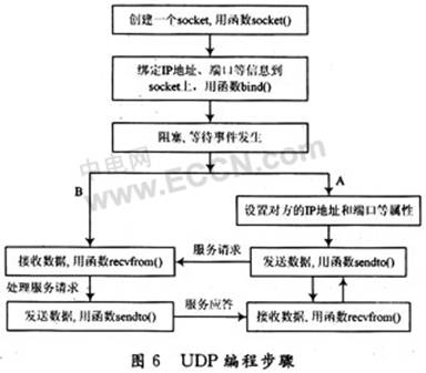
(1) The two parties establish sockets and call socket functions:
s = socket (PF_INET, SOCK_DGRAM, 0)
SOCK_DGRAM indicates that the socket type is a datagram socket, that is, the UDP protocol is used for communication.
(2) Bind the set own address and port information, and call the bind function:
bind (s, (struct sockaddr *) & my_addr, sizeof (structsockaddr))
(3) Put the select function in a blocking state until a file descriptor in the file descriptor set rfds changes:
select (pCtrl-> rwd + 1, & rfds, IFX_NULL, IFX_NULL, NULL)
(4) Data transmission: sendto () and recvfrom () are used for data transmission in the socket-less datagram socket mode. Since the local socket does not establish a connection with the remote machine, the destination address should be specified when sending data. As shown in Figure 6, A, as the sender, sends its service request data to the designated port of receiver B through its socket function sendto (), and B receives the data through its socket function recvfrom () and processes After a good service request, the service response is sent back to A. At this time, A becomes the receiver, and A can continue to send data to B after receiving the response.
2.2 Realization of broadcast communication
Both broadcast and multicast are used to send UDP datagrams to multiple receivers, but broadcast does not have a complicated control process at the receiving end like multicast, so it is much simpler to implement than multicast. The following broadcast communications are implemented on the basis of peer-to-peer communications.
On the sender side, you only need to set the socket option to allow sending broadcasts, and then specify the destination IP as the broadcast address when sending. Specifically, the socket broadcast is allowed to be set by setting the broadcast option of the setsockopt function. When the setsockopt parameter optname is SO_BROADCAST, it means that the broadcast is enabled or disabled from the socket, when the parameter optval is 1, broadcast is allowed, and when 0, the broadcast is prohibited.
Part of the source code for system programming to achieve broadcasting is:
int bBroadcast = 1:
setsockopt (pCtrl-> nAdminSocket, SOL_SOCKET, SO_BROADCAST, & bBroadcast, sizeof (bBroadcast));
setsockopt (pConn-> nUsedSocket, SOL_SOCKET, SO_BROADCAST, & bBroadcast, sizeof (bBroadcast));
tO_addr. sin_addr. s_addr = inet_addr (WIRLESS_IP_BROADCAST);
/ * WIRLESS_IP_BROADCAST is the broadcast address, its value is to set the host ID part of the IP address of the network interface (ath0 in this system) to all 1, and the network ID part remains unchanged * /
tO_addr. sin_family = AF_INET;
According to [7], at the receiving side, the broadcast is generally received without any changes. However, in the experimental process implemented by this system, when the socket is bound to an IP address other than INADDR_ANY, the receiver cannot receive the broadcast and there is no error indication, that is, the local port address needs to be bound to the wildcard address INADDR_ANY Receive broadcast:
my_addr. sin_addr. s_addr = htonl (INADDR_ANY);
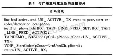
In addition, the system also implements the broadcast intrusion function, that is, regardless of whether the user is currently off-hook, dialing, or talking, when there is a broadcast call, the original connection is disconnected and a new connection is established with the broadcast caller ( Users do not need to hang up). In order to prevent confusion in the call, the system sets that only users with broadcast control rights have the right to speak at the same time, while other users can listen and cannot speak. When other users want to speak, they can grab the broadcast control right by pressing the "*" key Finally, the broadcast stops only when a user with broadcast control right hangs up, and any other user hangs up without affecting broadcast communication.
See Table 1 and Table 2 for part of the source code of system programming to achieve broadcast intrusion. 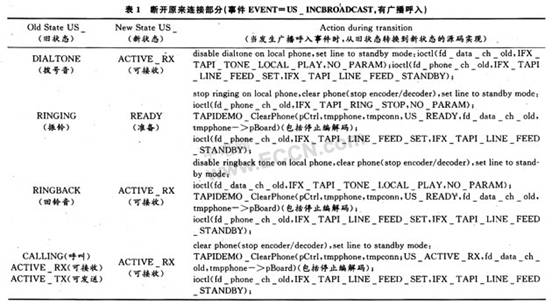
3 Conclusion
After the system design is completed, it is successfully applied to a power plant in Changde City for production scheduling. The system can realize point-to-point communication and broadcast communication, and the call quality is good, with no noise and jitter.
The system can self-organize the network due to its own wireless network card. It can be used as a wireless command dispatcher in factories with communication plugs. In addition, it can also be connected to an external speaker to automatically answer the phone. The machine operator does not need to stop his work. Follow the instructions to perform the corresponding operations. In addition, the application of this system has good scalability, for example: the system can be connected to the traditional PSTN through the FXO connection through the PCM channel (see Figure 1); transplanting the SIP protocol stack on this system can realize the communication with the WIFI mobile phone; The system is integrated into the Ad Hoc network, and various mobile terminal devices based on the Ad Ioc network can come into being, so this system has broad market prospects.
Rated current of Power Filter: 0.5A~300A
Various terminals of Radio Noise Filter: wire, solder lug, stud, terminal blocks, etc
Optional medical versions(H type)
Custom specific versions available on request
Features and Benefits:
General purpose filters with good attenuation performance at frequency range 150KHz~30MHz.
Compact structure, high performance-cost ratio, easy to install, safe and reliable. FT110 and FT111 series are one-stage common mode general purpse filters with almost the same filtering effect, only slight difference according to different current.
High voltage versions above 380VAC are also available.

EMI Filter Design,General Purpose Filter,Power Filter,Radio Noise Filter
Jinan Filtemc Electronic Equipment Co., Ltd. , https://www.chinaemifilter.com