
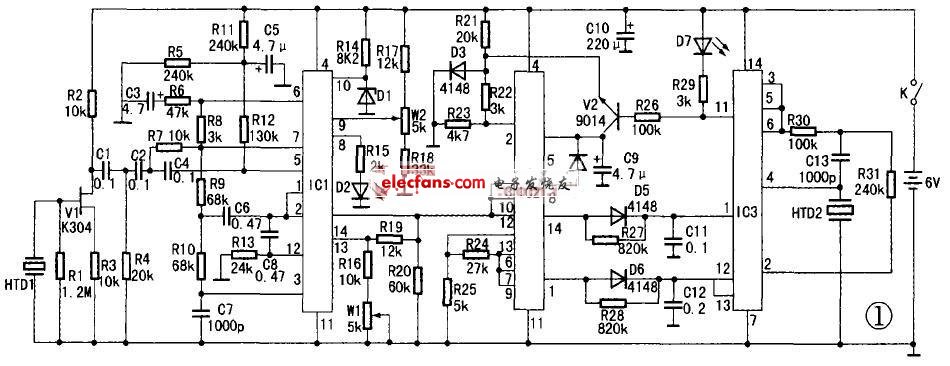
The circuit is shown in the figure below. The measuring instrument consists of sound wave acquisition, voltage amplification, low-pass filtering, waveform transformation, voltage detection, and sound and light display circuits.
This article refers to the address: http://
Component selection:
HTD1 uses 27mm piezoelectric ceramic sheets. IC1, IC2 select LM324 four op amps. IC3 selects CD4011 four NAND gates, D1 selects 4.5V voltage regulator tube, HTD2 selects 15mm piezoelectric ceramic sounder, K selects miniature toggle switch. D2 uses a miniature red LED, D7 uses a miniature blue high-brightness LED, and the power supply uses four AA batteries, and the remaining components are shown in the figure.
Instructions:
When using, attach the sphygmomanometer arm strap to your arm. Place the probe HTD1 on the radial artery under the arm band. When the air pressure is estimated to be greater than the systolic pressure (commonly known as high pressure) of 2.5 to 4 kPa (20 to 30 mmHg), stop the pressure, open the deflation valve and slowly deflate. When the air pressure drops to the systolic pressure, the measuring instrument starts to sound, and the light indicates the time. The blood pressure value displayed on the sphygmomanometer is the systolic blood pressure, and the sound and light are synchronized with the pulse beat. The blood pressure value displayed on the sphygmomanometer when the sound and light is stopped is the diastolic pressure.
Working principle: HTD1 sends the detected pulse beat sound wave signal to the gate of V1, where V1 acts as impedance transformation. Convert the weak acoustic signal voltage of high internal resistance to a lower impedance output, and couple it to IC1 via C1, C2, and C4. IC1 is a quad op amp, and its internal circuits and peripheral components of 5, 6, and 7 pins form a voltage amplifier. Changing the resistance of R8 can adjust the amplification factor of this stage. The amplified audio signal is coupled to a low-pass filter composed of internal and external circuits of 1, 2, and 3 pins via R9 and C6 to eliminate human body induction and external interference signals. And improve the load capacity. The signal is output from pin 1, and is coupled to 12, 13, and 14 by C8 for shaping and amplifying, and transforming the pulsed sound wave into a square wave output by 14 feet. Adjust w1 to change the amount of amplification. The square wave signal from the 14-pin output is directly coupled to pins 3 and 12 of IC2. After being amplified by two op amps, they are output by pin 1 and pin 14, respectively. The square wave voltage output from pin 1 is coupled to pin 12 and pin 13 of IC3 via D6. IC3 is a four-NAND circuit. When the 12 and 13 pins are high, the 2 pin outputs a low level. D7 lighting instructions. Adjusting the capacity of C12 can change the illumination delay time of D7. The square wave pulse high level of the 14-pin output of IC2 is coupled to the 1 pin of IC3 via D5, and the internal and external circuits of 1, 2, 3, 4, 5, and 6 pins constitute an oscillator. When the 1 pin is high, the oscillator starts to vibrate and emits an audible sound. The oscillation frequency is about 2000 Hz. The 5~10-pin circuits of V2 and IC2 play the role of sound and light synchronization.
The 8, 9 and 10 pin circuits of IC1 form a voltage detector to prevent the measurement accuracy from being lost when the battery voltage is too low. D1 provides a 4.5V reference voltage for pin 10, and R17, W2, and R18 form a voltage divider. Adjust W2 to set the starting voltage value. When the voltage of pin 9 is lower than 10 feet, the 8 pin outputs a high level, and D2 emits light, indicating that the battery should be replaced if the voltage is too low. The auxiliary measuring device consumes a small amount of power and can be used for more than one year after replacing the battery.
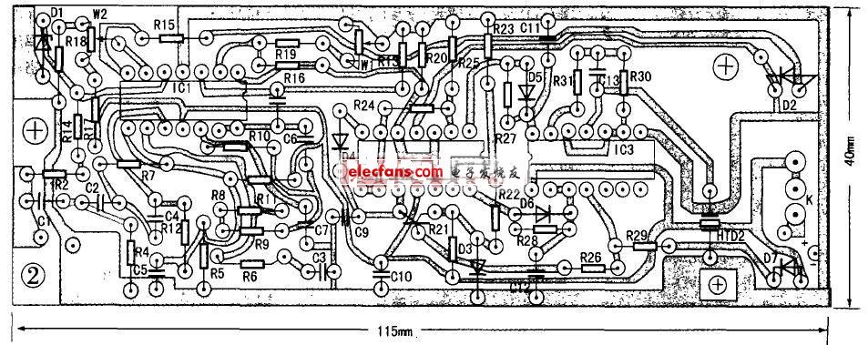
PCB board circuit
Digital currency transactions allow users to convert existing digital currencies into other digital currencies. The entire transaction does not involve any legal tender. Because of the relatively loose regulation, the mainstream digital currency trading platform also opened this function.Digital Asset Exchange (DAE) is a platform for matching transactions between digital currencies, digital currencies and legal currencies. It is the main place for encrypting the circulation and price determination of digital currency transactions.
Compared with traditional stock exchanges, digital asset trading platform not only matches transactions, but also plays the role of market maker and investment bank. The role of the market maker in the trading platform can increase the liquidity of the market, and the trading platform can earn the transaction price difference. The role of the investment bank of the trading platform is to provide services such as issuance and underwriting of digital currency, from which the trading platform collects money fees, or collects deposits in the form of community voting of the trading platform.
Currency Exchange,Digital Currency Exchange,Virtual Digital Currency Exchange,Display Currency Exchange
China youbi digital assets limited , https://www.ubcoinchina.com