
Tag: TD-SCDMA PDCP
This article refers to the address: http://
The location of the Packet Data Convergence Protocol (PDCP) in the Access Layer (AS) protocol stack is located above the RLC layer, and is subject to RRC scheduling and control, transmitting user data from the upper layer to the RLC sublayer. The service provided by the PDCP to the upper layer is the PDCP SDU delivery. The structure diagram of the protocol stack can be referred to the protocol 3GPP TS 25.301.
1 PDCP structure and function description
Figure 1 shows the detailed structure of the PDCP module. The Radio Access Bearers (RABs) of each PS domain are associated with 1 RB, and each RB is associated with 1 PDCP entity. Depending on the RLC mode, each PDCP entity can be associated with 1 or 2 RLCs, 1 PDCP can be associated with 2 unacknowledged mode/transparent mode RLC entities (1 upstream and 1 downstream) or 1 acknowledgment The mode (AM) RLC entity is associated. PDCP can use one type of multiple compression algorithm (RFC 2507 and RFC3095, currently only RFC2507) or no compression algorithm.
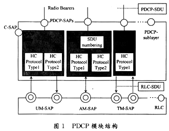
When the PDCP function is implemented, the PDCP can be divided into two sub-modules: the PDCP control part, which mainly performs processing on the PDCP control service access point, sends primitives through the PDCP and RRC interfaces, and generates, configures, and deletes the PDCP entity, RRC. Configure all parameters required for header compression for PDCP, and associate PDCP with RAB and RB. Second, PDCP user part mainly completes receiving data from RB, compresses the IP packet header on the uplink, and then sends it to the corresponding On the downlink, the PDCP receives the first compressed data from the RLC, decompresses it, and transmits it to the upper layer.
The functions implemented by the PDCP are as follows: First, the header compression and decompression of the IP data stream in the PDCP entity of the sender or the receiver. Header compression is for a specific network layer, transport layer, or upper layer protocol combination. When a PDP context is activated, the network layer protocol needs to be known. The PDCP can identify different types of header compression protocols by PID values. The PDCP configuration is set by the UTRAN; the transmission of user data, this function is used for data aggregation between users of the PDCP service. After the PDCP instance is configured successfully, data transmission can be performed. In the uplink data transmission process, the PDCP receives the data sent by the RABM, and assembles the data into a PDU according to the configuration information and sends the data to the RLC in the form of a primitive. After the PDCP receives the data sent by the RLC, the PDCP assembles the data into a PDCP SDU and sends it to the RABM entity. If the PDCP is applied to the SRNS relocation, the PDCP needs to save the SDU sequence number for the RB. No loss SRNS relocation is supported only when the RLC is configured for acknowledge mode (AM) and sequential transmission. Although RLC provides a reliable data transmission service, when SRNS relocation does not guarantee the reliability of transmission, PDCP needs to save the PDCP sequence number during SRNS relocation to avoid data loss.
2 PDCP interface description
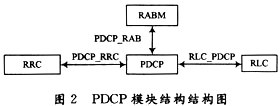
The interface structure diagram is shown in Figure 2. The PDCP interface is mainly connected to the RRC, the RABM, and the RLC, and configures the required parameters for the PDCP through the PDCP_RRC interface RRC. After completing the related operations of the control part, the PDCP completes the data transmission between the RABM and the RLC through the PDCP_RAB and the RLC_PDCP interface, and implements uplink and downlink data transmission.
3 process implementation
3.1 PDCP data transmission process (RLC_AM mode)
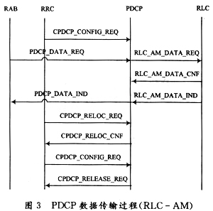
The UE starts data transmission. First, the PDCP is in an empty state, and the RRC does not configure the PDCP. The RRC sends a primitive of "CPDCP_CONFIG_REQ" to the PDCP to configure the PDCP instance, and prepares to send and receive data after retaining the configuration parameters. The RRC then informs the RABM to perform data transmission. The RABM sends the data to the PDCP as the "PDCP_DATA_REQ" primitive. The PDCP will perform IP header compression and other operations, assemble the PDCP SDU into PDCP PDU, and send it to the RLC instance with the "RLC_AM_DATA_REQ" primitive. . If no loss SRNS relocation is supported, the PDCP receives the "RLC_AM_DATA_CNF" message; if the indication PDU is successfully sent, the PDCP will release the data; if not, the PDCP needs to resend the data. This message can be omitted if no lossless SRNS relocation is supported. Then, the PDCP receives the "RLC_AM_DATA_IND" message of the RLC, decompresses the PDU, etc., and assembles the primitive into "PDCP_DATA_IND" to send the RABM entity. If the PDCP is configured with no loss SRNS relocation, the serial number needs to be maintained and can be operated by the "CPDCP_RE_LOC_REQ/CNF" primitive. In the data transmission process, if the RRC needs to reconfigure the PDCP instance, send "CPDCP_CONFIG_REQ" to perform the operation. After the data is sent and received, the RRC sends a "CPDCP_RELEASE_REQ" message to the PDCP to release the PDCP instance, and the PDCP returns to the empty state.
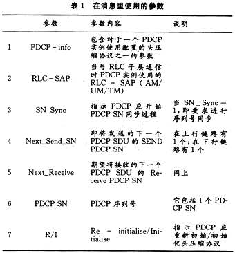
The above various messages contain some parameters, and the parameter list is shown in Table 1. Figure 3 shows the PDCP data transmission process of RLC-AM.
3.2 PDCP data transmission process (UM-RLC mode)
The PDCP data transmission process of the UM-RLC is substantially the same as the AM-RLC process, and will not be described in detail herein. The difference is that when the PDCP is transmitting uplink data, the PDCP assembles the SDUs sent by the SABM into PDUs and sends them to the RLC in the form of "RLC_UM_DATA_REQ"; when the downlink performs data transmission, the RLC PDUs as "RLC_UM_DATA_IND" The primitive form is sent to PDCP. "RLC_UM_DATA_REQ/IND" and "RLC_AM_DATA_REQ/IND" refer to the protocol 3GPP TS25.322; since no RNS is configured in the AM mode and no SRNS relocation is supported in the sequential transmission, if no SRNS relocation is supported in the process, then The "CPDCP_RELOC_REQ/CNF" and "RLC_AM_DATA_CNF" messages will be considered invalid during this process.
3.3 PDCP data transmission process (TM-RLC mode)
The PDCP data transmission process of the TM-RLC is basically the same as the UM-RLC process. The difference is that the PDCP sends the SDU sent by the upper layer into the PDU and then sends it to the RLC as RLC_UM_DATA_REQ. When the downlink data is transmitted, the RLC sends the data to the PDCP as RLC_UM_DATA_IND.
4 Conclusion
The TD-SCDMA standard is the first international communication standard proposed and adopted by China to the ITU. It has unique advantages in spectrum utilization, service support flexibility and cost. In today's unprecedented development of user data services, only by meeting the needs of users and providing quality services can we better occupy the market. PDCP is the sub-layer of L2 in the user data plane. This paper describes its structure, function and implementation process. It is helpful for understanding the PDCP sub-layer function and PDCP project implementation.
Small Pitch LED Display is also called HD Led Display Screen. In recent years, the wide application of Led Display screen in all walks of life has led to the centralized outbreak of "small spacing", especially in places where the display requirements, screen precision and density requirements are relatively high, such as police command system, monitoring and security system, high-end conference system, advertising information release, etc.

Small pitch LED display is so popular, mainly because it has the following outstanding characteristics:
1.Cabinet thickness of the box <40mm;
2.Cabinet power no cascade output, lower risk of connection defectives;
3.Secondary class power supply design, low voltage power supply inside cabinet,high efficient module power,
low heat radiation;
4.The module apply magnesium alloy die-casting bottom base, good flatness, the bottom base dings;
5.Module intelligent detection and data;
6.Board-to-board professional connector for module and HUB, the performance is more reliable;
7.Control card and power supply using dual backup design, it can be applied to a variety of high demand places;
8.Concealed HDMI connection for signal more stable performance and cleaver joint;
9.Front and after maintenance for control cards;
10.High gray level, high refresh, high contrast, low brightness design.

Small Pitch LED Display
Small Pixel Pitch LED Display,Professional Led Manufacturer,HD LED Screen
Shenzhen Vision Display Technology Co,.LTD , https://www.ledvdi.com