
With the development of various electric vehicles, the demand for power battery chargers will increase. The quality of the charger is related to the performance of the battery and the longevity of the battery. The intelligent nature of the charger itself is related to the user's ease of use and power system billing. Different batteries, different characteristics, charging strategies are also different. If a battery charger is completed, it is easy to expand the technology to other battery types. This topic has practicality and is also targeted at the training of talents in the field.
This article refers to the address: http://
Main functional indicators:
★ input voltage single phase 50HZ ± 10%, voltage effective value fluctuation range 220V ± 20%, that is, the effective value is 176V-264V;
★ Output DC rated voltage 50V;
★ Input power factor correction, power factor 90%;
★ The initial efficiency of charging is greater than 80%;
★ input current distortion is less than 4%;
★The charging process is divided into exciting, fast charging and floating charging;
★ With temperature detection function, it can change the charging strategy according to battery and ambient temperature;
★ With a friendly man-machine interface, the charging strategy can be adjusted;
★ Cooling method: air-cooled.
The overall block diagram of the main circuit:
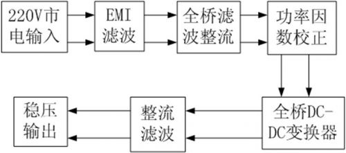
EMI filter circuit:
C1 and L1 form the first stage EMI filter
C2, C3, C4 and L2 form a second level of filtering.
L1, L2 are common mode inductors
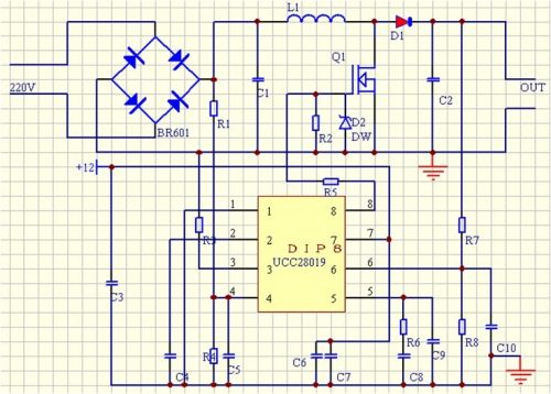
Rectification and power factor correction circuit:
Rectifier bridge:
Flow through diode current ID=3.55A
Diode reverse voltage V=373V
Consider the actual working conditions, choose BR601 (35A/1000V);
Power factor correction:
Solution: BOOST topology has low output resistance, simple hardware circuit and control, and mature technology, so BOOST structure is selected;
Chip selection: TI's UCC28019 can control the power output to 100W-2KW, the power factor can be increased to 0.95, in line with the design requirements, so this design uses this chip;
Circuit diagram
DC-DC main topology:
plan selection:
In the case that the switch tube is subjected to peak current and voltage, the full bridge output power is twice that of the half bridge, and when the power is greater than 500 W, the full bridge is more suitable than the half bridge, so this design adopts a full bridge topology.
Power switch tube selection:
After rectification and filtering, the maximum voltage is 373V, and the maximum primary current is 3.5A. Consider the actual working condition and choose FQA24N50.
(24A/500V/0.2Ω)
Output rectifier diode:
The maximum reverse voltage of the rectifier diode is 100V and the current is 10A. Considering the actual working conditions, we choose MUR3060 (600V/30A).
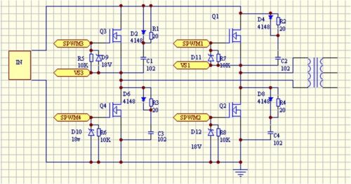
Full bridge circuit diagram:
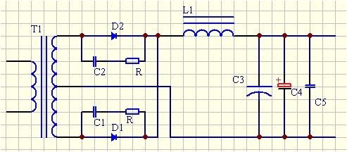
Rectifier filter output circuit:
Drive circuit:
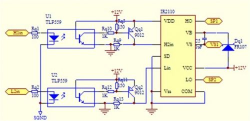
The PWM signal is isolated by the optocoupler and enters the half-bridge driver chip IR2110 through the inverter. The Q1 and Q2 half-bridge drive circuits are shown in the figure. The Q3 and Q4 drive circuits are the same as this circuit.
Auxiliary power supply:
The design system is powered by an auxiliary power supply. The system block diagram is as follows:
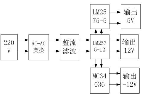
The power supply system can provide stable 12V, 5V, -12V voltage and high efficiency.
Intelligent control circuit design:
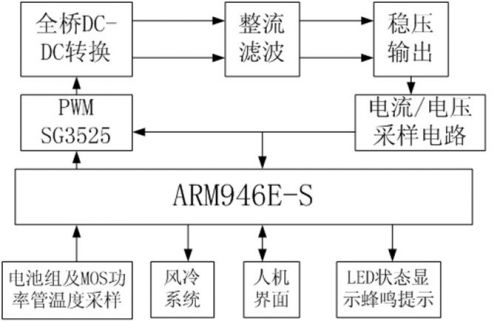
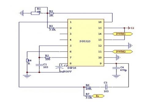
Power supply PWM control section
The chip used in the power core control part of this design is the US General Motors chip SG3525. The control circuit is as follows:
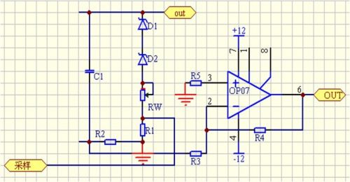
Sampling circuit

Thermal protection circuit
The design system can detect the battery temperature and the charger temperature. When the battery is over temperature, the PWM output waveform will be turned off, so that the circuit stops working, and the MCU will alarm. When the charger is over temperature, the air cooling system will turn on if the temperature Continue to rise, the charger will stop working.
Overcurrent, short circuit protection circuit
When the current is too large, more than 12A, the circuit will limit the flow alarm, and the short circuit detection will be performed before the charger starts. When the resistance is less than 0.5Ω, the circuit is considered to be faulty and an alarm is given.
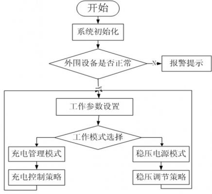
System software structure
Four-stage charge control strategy:
Four-stage charging strategy analysis:
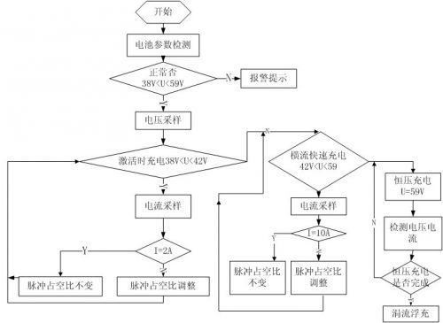
Activate charging: After the charger starts working, the MCU collects and collects the battery terminal voltage detection. If the voltage is too low, it indicates excessive discharge. To avoid excessive charging current, a small current activation is implemented.
Constant current charging: constant current charging is 10A.
Constant voltage charging: constant voltage charging voltage is 59V.
Turbulent floating charge: When the charging current drops to 0.1 times of constant current, that is, 1A, turbulent floating charge is used.
The four-stage charging strategy ensures that the battery can be activated and repaired at the initial stage of charging, so that the battery is more durable and not fully charged at the end, and can achieve full purpose.
Power system anti-interference
Hardware anti-jamming technology
Power supply EMC design: The rectifier diode uses Schottky diode as the rectifier, the switch loop plus RCD network, and the input end plus EMI filter circuit to optimize the transformer design.
Optimize PCB layout and routing.
Software anti-jamming technology
Adopt remote interception technology between program modules.
Pcb Speaker,Pcb Subwoofer,Pcb Mount Speaker,Pcb Mounted Speaker
NINGBO SANCO ELECTRONICS CO., LTD. , https://www.sancobuzzer.com