
The tube has a knee pressure. In the output characteristic curve (Fig. 1-3), after the load becomes larger, the intersection point between the load line and the output characteristic curve becomes smaller, and the voltage of the knee point shifts to the left, so that the swing of the voltage can be increased (otherwise, the same Input will be over pressure). The probability that the signal is distributed near the mean value is large, and the probability that the signal is too large or too small is relatively small.
In today's world, the development of communication technology can be described as ever-changing (accurately, human desires are changing with each passing day). However, the wireless communication that humans rely on now is entirely radio, and the frequency bands are mostly concentrated below the C-band, which is quite crowded. Then, in order to increase the amount of information transmission in a limited spectrum resource, the signal modulation method becomes more and more complicated, and many non-constant envelope modulation methods such as 64QAM and 256QAM appear, so that the peak-to-average ratio of the signal is continuously Become bigger. Figure 1-1 is a comparison of the instantaneous envelope probability distribution of the signal envelope with the instantaneous efficiency curve of the class AB amplifier (for comparison with the AB class? Because the base station amplifier is of this type not too long ago).
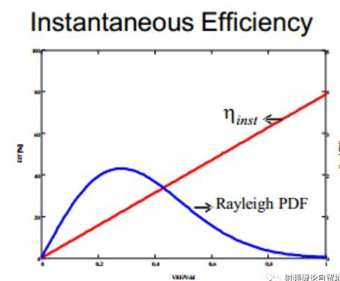
Figure 1-1 Envelope efficiency and envelope probability distribution of class AB amplifier
It is not difficult to see that the probability that the signal is distributed near the mean value is large, and the probability that the signal is too large or too small is relatively small. However, it can also be seen from the figure that the efficiency of the class AB power amplifier increases as the signal power increases, so the efficiency of the power amplifier is very low near the mean value. When a base station power amplifier uses a class AB power amplifier, it often needs to retreat from P-1dB by about 6dB. At this time, the efficiency will be reduced from 50% to 20% (for example, not to determine the data), don't underestimate, if It is required to output a rated power of 100W, and you calculate how much power is going to heat up. . Therefore, the traditional class AB power amplifier can not meet the requirements of modern communication systems for power amplifier efficiency. Therefore, it is necessary to design a high-efficiency power amplifier to meet the system's demand for efficiency. Maybe you will say how difficult it is to use switch-type power amplifiers (such as Class E), harmonic control class power amplifiers (such as Class F), the theoretical efficiency is 100%. But unfortunately, the linear correction of these high-efficiency power amplifiers is difficult, and the DPD is directly killed (the algorithm needs to be refueled...), and the working bandwidth of these high-efficiency power amplifiers is not enough, and the reliability is not it is good. Fortunately, in the days of nowhere, fortunately, as early as 1936, Mr. WHDoherty invented the Doherty amplifier architecture. This kind of architecture power amplifier can have higher efficiency and better linearity at the same time when the power amplifier is backed up. What is the principle of such a powerful power amplifier architecture? The following is a step-by-step deconstruction of the Doherty power amplifier architecture. (The following explanations are for students who have an understanding of the working principle of the power amplifier tube. Students who don’t know how the power amplifier works can stop, and make up the basics. first...).
Load traction principleBefore explaining how Doherty works, let's talk about its lifeblood -- load traction. So what is load traction? We all know that there is a static working point and load line when the power is working. Take the power amplifier tube biased in class B as an example. It is intended to be shown in Figure 1-2 under a fixed load.
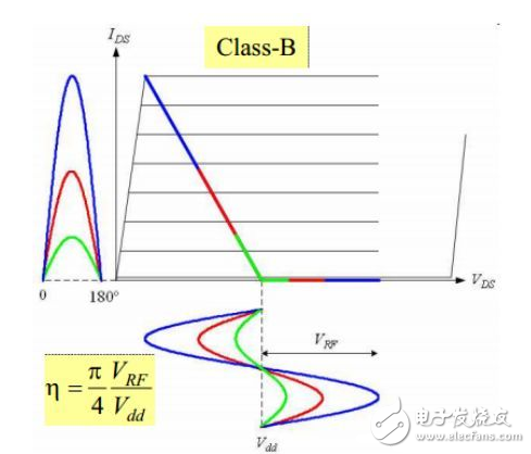
Figure 1-2 Schematic diagram of fixed load
It can be seen from the figure that the drain current is a cosine pulse, that is, the power amplifier does not have an overvoltage, and the operation is in an undervoltage state. This premise is important because the ratio of the fundamental current to the direct current in the efficiency calculation at this time is important. It has been determined by the bias, and the efficiency of the power amplifier is proportional to the swing of the RF voltage of the drain (the specific explanation is written in a large part, and there is a space to re-code). Therefore, in order to achieve high efficiency, the power amplifier should be in a voltage saturation state, that is, the RF voltage swing should be close to the drain power supply voltage. The signals of several different colors in the figure represent different input and output powers. It can be seen that the smaller the output power, the lower the efficiency (small voltage swing). However, our need is to achieve high power amplifier efficiency in the input signal averaging area, which means that the voltage swing can be close to the drain supply voltage when the input signal is small. This is not possible with fixed bias and load impedance. So now if you want the bias state to be the same, what should you do to achieve high efficiency? You may have discovered that the way to achieve this is to increase the load on the amplifier and allow the power to be saturated at a lower output power level for high efficiency. This is called load modulation. Figures 1-4 are schematic diagrams of load modulation.
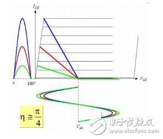
Figure 1-3 Schematic diagram of load modulation
It can be seen from the figure that as the load becomes larger (from blue to green), the drain voltage swing of the power amplifier is closer and closer to the drain power supply voltage, and the efficiency of the power amplifier is getting higher and higher. By choosing the right load impedance, the amplifier can be placed at high output efficiency.
This time I said so much, some of the premise of the statement I did not mention, such as the harmonic short-circuit condition of the power amplifier, etc., the purpose is to first clear the load modulation. If you have other questions and knowledge, please discuss it. The next time I will talk about the specific working process of the classic two-way symmetric Doherty.
Shenzhen GEME electronics Co,.Ltd , https://www.gemesz.com