
An all-electric vehicle without an internal combustion engine requires a safe, cost-effective and high-capacity energy storage system. Efficient software algorithms, powerful microcontrollers and high-efficiency motors make the most of existing energy sources, and high integration helps achieve a leaner and lower cost motor control system. Designed for hybrid and electric vehicles, a new generation of highly integrated MCUs includes timing structures that generate motor control signals and a variety of I/O ports and interfaces.
Figure 1 shows a broad classification of hybrid and electric vehicles. The core element of hybrid and electric vehicles is the motor in the transmission system, which is deployed in a hybrid vehicle with a conventional internal combustion engine and as an independent source of kinetic energy in an electric vehicle. Choosing a motor requires careful analysis of size, weight, reliability, durability, required torque and overall efficiency.
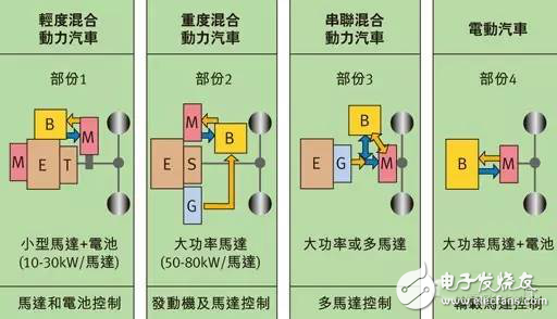
Figure 1: Classification diagram of hybrid and electric vehicles.
There are two basic types of motors that are suitable. One is an asynchronous motor that is durable and reasonably priced because they do not require magnets made from rare earth elements. Its characteristic parameters can be controlled by software algorithms and do not require maintenance. This motor is slightly less efficient than a synchronous motor and has a lower torque at start-up. The disadvantage is that the efficiency is slightly lower, about 90%, and the weight is heavier.
Another suitable motor is a permanent magnet synchronous motor (PMSM) with high torque, tight dimensions and high efficiency of nearly 94%. Synchronous motors are costly due to the need for permanent magnets made from rare earth elements. Brushless versions of asynchronous motors and permanent magnet synchronous motors have no problem with brush loss. Permanent magnet synchronous motors offer better size/torque ratios and higher efficiency and are the first choice for electric and hybrid automotive transmission systems.
control
As mentioned earlier, both motors have a brushless version. Although this brushless motor requires more rectification, it provides safe and efficient control, which is fundamental and primary in the transmission system. The current challenge is to achieve the perfect balance of motors, power electronics, control units (microcontrollers) and control software. The algorithms used must be adapted to the respective motor and application, allowing the electronic controller to optimize motor rectification at all times. Failure to properly adapt can lead to adverse effects, such as irregular execution and excessive noise, which can have a certain negative impact on efficiency. Motor control includes various control algorithms for different applications.
Sensor-based rotor position sensing can be implemented by a variety of sensing systems. In general, detecting the position of the rotor is critical to precise motor control. As an important component, rotor position sensors have a significant impact on the performance and efficiency of the motor system. The Hall position sensor is based on the Hall effect and induces a voltage by changing the magnetic field around the current carrying conductor. With the help of the rotor magnetic ring and the sensor device attached to the rotor, the Hall effect sensor is a convenient and inexpensive method for detecting angles. The greater the number of poles and Hall components, the higher the resolution and accuracy and the more susceptible to magnetic field interference.
Incremental encoders are a common sensor that is used in a wide range of designs, with mechanical and optical scanning characteristics to determine the current angular position. When measuring angles, the incremental encoder must be based on a zero position or reference position. For a microcontroller, the actual angle measurement involves only detecting the direction of rotation and the divergence of the operational pulses. The angular velocity can be calculated by simply measuring the time interval between two pulses. The non-inductance of electromagnetic interference is very beneficial; on the contrary, any mechanical friction loss and susceptibility to dirt are disadvantageous in optical systems.
Decomposer
The resolver is a rugged sensor commonly used in the automotive industry, immune to magnetic field disturbances and dirt, and is immune to frictional losses during angle detection. It consists of a wheel permanently attached to the motor shaft (motor rotator) and an annular stator permanently attached to the motor casing. The stator includes at least one excitation coil and two sensor coils. Higher resolution can be achieved by increasing the number of pole pairs.
Figure 2 shows the resolver. The excitation coil is equipped with an analog sinusoidal signal. The analog signal is transmitted to the two sensor coils via magnetic coupling (induction) and placed at 90 degrees to each other. Evaluation of the analog sine and cosine signals returned by the resolver requires a shaft angle digitizer (RDC) that is used to determine the angular position and velocity from the simulated data.
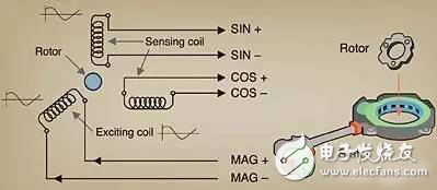
Figure 2: Decomposer schematic and mechanical structure.
Decomposers may not be superior in performance and accuracy to other competing technologies, but they are more durable and provide better protection in environments such as dirt and extreme temperatures. Even in the stationary state, it can detect the absolute position of the motor at any time, while incremental encoders and Hall sensors cannot perform this function.
SAMSUNG Nozzle
Original and new, in stock,quality guarantee, fast delivery
SAMSUNG CP20/40 Part Number Description
SAM-N045 SAMSUNG PICK UP NOZZLE Ø 1.0 / Ø 0.45 (BLACKEN)
SAM-N08 SAMSUNG PICK UP NOZZLE Ø 1.5 / Ø 0.8 (BLACKEN)
SAM-N14 SAMSUNG PICK UP NOZZLE Ø 2.7 / Ø 1.4 (BLACKEN)
SAM-N24 SAMSUNG PICK UP NOZZLE Ø 4.0 / Ø 2.4 (BLACKEN)
SAM-N40 SAMSUNG PICK UP NOZZLE Ø 6.2 / Ø 4.0 (BLACKEN)
SAM-N75 SAMSUNG PICK UP NOZZLE Ø 9.0 / Ø 7.5 (BLACKEN)
SAMSUNG CP45FV
TN03 SAMSUNG CP45 PICK UP NOZZLE - Ø0.8/Ø0.28 (TN03)
J7055246A SAMSUNG CP45 PICK UP NOZZLE - Ø0.75/Ø0.38 (TN04)
J7055267A SAMSUNG CP45 PICK UP NOZZLE - Ø1.2/Ø0.65 (TN65)
J7055131C SAMSUNG CP45 PICK UP NOZZLE - Ø2.2/Ø1.4 (TN14)
J7055132C SAMSUNG CP45 PICK UP NOZZLE - Ø3.6/Ø2.2 (TN22)
J7055133C SAMSUNG CP45 PICK UP NOZZLE - Ø6.2/Ø4.0 (TN40)
J7055135C SAMSUNG CP45 PICK UP NOZZLE - Ø9.0 / Ø7.5 (TN75)
J7055137C SAMSUNG CP45 PICK UP NOZZLE - Ø12.7/Ø11.0 (TN110)
SAMSUNG CP45 NEO
J9055133B SAMSUNG CP45 NEO PICK UP NOZZLE - Ø0.8/Ø0.28 (CN030)
J9055134B SAMSUNG CP45 NEO PICK UP NOZZLE - Ø0.75/Ø0.38 (CN040)
J9055135B SAMSUNG CP45 NEO PICK UP NOZZLE - Ø1.2/Ø0.65 (CN065)
J9055138B SAMSUNG CP45 NEO PICK UP NOZZLE - Ø2.2/Ø1.4 (CN140)
J9055139B SAMSUNG CP45 NEO PICK UP NOZZLE - Ø3.6 / 2.2 (CN220)
J9055218A SAMSUNG CP45 NEO PICK UP NOZZLE - Ø6.2 / 4.0 (CN400N)
J9055142B SAMSUNG CP45 NEO PICK UP NOZZLE - Ø9.0 / 7.5 (CN750)
J9055143B SAMSUNG CP45 NEO PICK UP NOZZLE - Ø12.7 / 11 (CN110)
SAMSUNG CP60
J9055069B SAMSUNG CP60 PICK UP NOZZLE - Ø0.8/Ø0.3 (TN030)
J9055070B SAMSUNG CP45 NEO PICK UP NOZZLE - Ø0.75/Ø0.38 (TN045)
J9055071B SAMSUNG CP45 NEO PICK UP NOZZLE - Ø1.2/Ø0.65 (TN070)
J9055072C SAMSUNG CP45 NEO PICK UP NOZZLE - Ø2.2/Ø1.4 (TN140)
J9055073C SAMSUNG CP45 NEO PICK UP NOZZLE - Ø3.6/Ø2.2 (TN220)
J9055074C SAMSUNG CP45 NEO PICK UP NOZZLE - Ø6.2/Ø4.0 (TN400)
SMT Nozzle For Yamaha
Yamaha Nozzle
Nozzles For Yamaha Machine
SMT Yamaha Nozzle
SMT SIEMENS Nozzle
Nozzles For Siemens Machine
SMT Nozzle For Siemens
SIEMENS Nozzle
SMT Nozzle For Samsung
SAMSUNG Nozzle
Nozzles For SAMSUNG Machine
SMT SAMSUNG Nozzle
PANASONIC Nozzle
Smt Samsung Nozzle,Samsung Nozzle,Nozzles For Samsung Machine,Smt Nozzle For Samsung
Shenzhen Srisung Technology Co.,Limited , https://www.sr-smts.com