
Mentor Graphics, a leader in electronic design automation technology, recently released a research report titled "Overall Solutions for Automotive System Design." The full text of the Chinese version of the report can be read and downloaded from the official website of Mentor Graphics: http://automotive.cn.mentor.com/news-publications/holistic-approach-vehicle-system-design.
This article refers to the address: http://
background:
A vehicle system design method that uses standardized, hierarchical functions as a single level to describe electrical, electronic, and software content is presented. The execution level of the specific domain is then generated in a synthesis process and evaluated using the appropriate metrics. The focus is on rapid iterative optimization and evaluation and verification of cross-domain architectures.
Summary
A vehicle system design method that uses standardized, hierarchical functions as a single level to describe electrical, electronic, and software content is presented. The execution level of the specific domain is then generated in a synthesis process and evaluated using the appropriate metrics. The focus is on rapid iterative optimization and evaluation and verification of cross-domain architectures.
Function-based system engineering
Introducing and developing system architectures in a functional way is usually based on a domain-specific language derived from UML (Unified Modeling Language) such as EAST-ADL or SysML. At the same time, the technical content (components) of the system to be developed is introduced in various forms and abstraction levels (such as functions, activities, sequences, and/or state diagrams) and then appropriately mapped for execution.
Using this method requires a lot of work, is not suitable for architectural evaluation, and is more suitable for detailed archiving. In fact, in order to be able to make meaningful technical and financial assessments of the overall system architecture, each individual level must be clarified in great detail until a sufficient level of detail is reached. In subsequent mappings, the workload is increased by the square of the level of detail: for example, the number of artifacts in a single hierarchy.
If the corresponding metrics are not sufficiently agile, it is not possible to evaluate changes in functional allocations in a timely manner, and it is not possible to provide truly meaningful results for each individual choice to be evaluated, such as a software component of a specific control unit.
Overall, this has greatly affected the study of architecture. In some cases it may take more time to provide the necessary data and calculate the desired indicator than the original project planned!
Functional model
Another approach introduced uses a standardized, hierarchical functional model at a single level to describe the technical content of the system architecture. Standardized functional models refer to individual functions that can be separated from their final execution as hardware, drives, and software components. Models are no longer distributed at multiple (and in some cases redundant) levels, but instead a single specific domain description can be combined with a single functional abstraction, eliminating the lengthy mapping process. Communication between individual functions is achieved by signals that can be standardized (becomes software, electrical or bus signals). All artifacts can be related to a set of rules from a detailed option/variant model. Component models of hardware, software, and electronic & network communications can thus be integrated and use Design Rule Check (DRC) to simultaneously examine and validate their semantic dependencies.
In this way, the technology of the downstream execution domain (hardware, software, network, and electrical), the variant-driven content can be captured early in the functional abstraction hierarchy, and verified in all variants.
To illustrate this approach, Figure 3 shows a number of functional blocks. Software functions (SW), driver components (D), sensors (S) and actuators (A) are described and displayed at a single level of abstraction. The signals between functions are displayed according to the color they need to perform: red (SW), green (electronic signal on the PCB), orange (electronic signal on the harness), and blue (signal on the network).
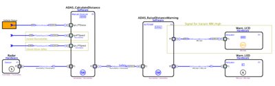
Function diagrams for various functions, option assignments, and external function blocks or signal references
In Figure 4, the assignment of a single type is consistent with the execution requirements of the downstream platform. If a function belongs to a software class, this means that the function is considered a SW component in the downstream allocation on the platform: it should be assigned to the control unit instead of a pure electrical component. Note that some features and information are optional and correspond to the option/variant model.
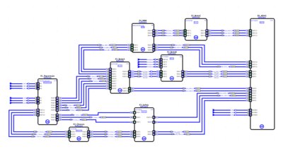
Diagram of different software class functions
Functions can be organized hierarchically, with functional signals either referring to their original function (if starting with an external functional design) or through a signal library for cross-platform and project use.
Logical platform
If the functional design is captured as described above, downstream execution (hardware and software, serial bus system, and electrical distribution) can be automatically created and the option/variant relationship will always be respected.
To do this, first define a logical platform. This can be obtained from a 3D model in the form of a physical topology, but can also start with an abstract logical network topology. By assigning a single functional component to an option/variant model, the logic platform can include (in the case of automotive engineering) all possible derivatives of a single car, a series of cars or an automotive platform, including software, electrical systems, Network and hardware variants. The same principles apply to trucks, off-road vehicles, airplanes and complex electromechanical devices such as industrial printers and medical equipment. Even an extended system like an air defense system can be modeled this way.
A single node of the platform is standardized as a resource: an electronic control unit (ECU) or a line replaceable unit (LRU), an electrical assembly, an electrical or ground conductor. They can be coupled via electrical or bus systems (CAN, LIN, Flexray, Ethernet, ARINC 429, etc.) or via optical or radio wave connections. These communication paths are referred to as carriers.
synthesis
The function is then assigned to the logical platform. This can be done manually or automatically using rules. The function will be queried according to the type of function during execution. For example, create a software component from the SW type and then assign it to the control unit. The signals passed between functions are divided into software, electrical or network signals on the logical platform.
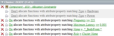
Rules for assigning functions
Rules for assigning functions and signals
The resulting synthesis is a four-category domain (hardware, software, network communication, and electrical) that integrally performs functional descriptions. Analyze semantic consistency in real time with design rule checks, any necessary warnings, or generated error messages.
index
Technical assessment indicators can be calculated as early as the synthesis process. These indicators can be displayed with various information by setting. For example, metrics that are meaningful for multiplexed networks include load, fault tolerance, and overhead. Indicators for the electrical domain include wires, solder joints and connectors, wire length, and harness diameter. Control unit specifications include equipment weight, CPU load, RAM, ROM, FLASH/EEPROM requirements, printed circuit board (PCB) area and unit volume power, and heat dissipation. The metrics are calculated by parameters related to functions, resources, and carriers: these parameters can often be learned in detail from previous implementations.
If a value is greater than a certain level, for example, if the predicted memory requirement exceeds the budget proposed by the microprocessor, this condition will be sent through the design rule check or directly to the platform architect's graphical display. This helps the engineer to ensure the feasibility of the design.
And it's not just technical indicators that can be calculated. By expanding the calculations, you can also calculate project goals such as cost, weight, margin, reliability, or reuse.
Evaluation and optimization
Because the use of these indicators for evaluation is done in real time, that is, when design decisions or changes are made, this process closely matches the evaluation of alternative execution (architecture) or actual modification of functional content. The indicators immediately reflect these changes, and then alternative research studies can be conducted.
It is therefore possible to iteratively and interactively solve optimization function partitioning, electrical optimization, cost and runtime optimization issues.
After the final evaluation, the results of the logical platform synthesis are delivered to the downstream detailed design process in the form of each specific domain (eg ARXML, FIBEX or KBL). The results of the architecture research phase can be reused as implementation recommendations for future platforms. In an integrated design environment, data can of course be passed directly to the appropriate application.
to sum up
The approach presented uses functional abstractions at a single level to integrate different electronic/electrical domains. This in turn allows for a quick assessment of the execution of other scenarios while preparing data for detailed design.
Because of the high requirements for technical work and knowledge, existing UML or similar SysML metamodel-based methods are not suitable for such architecture evaluation and verification. The associated complexity results in little or no sufficient detail necessary to provide a comprehensive evaluation within the time available.
Commercial software for the described principles can be found in the Mentor Automotive Capital® product suite.
In contrast, the described method uses a functional abstraction in which the execution of related data and artifacts is integrated into a standardized functional model rather than distributing them to different (and in most cases redundant) levels. .
As early as the automatic assignment to the logical platform, the model can be repeatedly verified for implementation feasibility and maintenance of the corresponding technical and commercial indicators. The result of the architectural process is also the implementation of the downstream development process for software, networking, electrical systems, and hardware.
Dog Training Collar,Petsafe Remote Trainer,Pet Gentle Ultrasonic Remote Trainer,Small Dog Training Collar With Remote
Elite-tek Electronics Ltd , https://www.aetertek.ca