
TPMS has a significant impact on improving vehicle safety. Tires are the only direct contact between the car and the road. Excessive inflation or under-inflated tires can affect vehicle safety. There are many car accidents caused by the condition of the tires. The US Highway Safety Association (NHTSA) has also legislated to enforce TPMS.
This article refers to the address: http://
Various TPMS system technologies and market conditions
Currently, there are three main implementations of TPMS: direct TPMS systems, indirect TPMS systems, and hybrid TPMSs that are being introduced.
The current indirect TPMS is used with the vehicle's anti-lock braking system (ABS). ABS uses a wheel speed sensor to measure the speed of each wheel. When the air pressure of a tire is reduced, the rolling radius is reduced and the rotational speed of the wheel is correspondingly accelerated.
This ratio can be expressed by the following equation (see Equation 1).
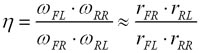
If this ratio deviates from the set tolerance, one or more tires will be too inflated or under-inflated. Then, the indicator light will prompt the driver that one of the tires is in a low pressure state. However, indirect TPMS has certain limitations. The first is that the indicator light cannot indicate which tire is in a low pressure state. Second, when the same axle or two tires on the same side are in a low pressure state, it cannot detect which tire is underinflated. Third, if all four tires are in a low pressure state, the system will not find this fault. In addition, the reduction in tire diameter and the decrease in gas pressure when the air pressure is insufficient are very small. For thin tires, a pressure drop of 69 kPa (~10 psi) will only reduce the diameter by 1 mm. This pressure drop does not meet the 25% principle set by the US Final Rule, and indirect methods rely heavily on tires and load factors.
The direct TPMS directly measures the air pressure of each tire using a pressure sensor fixed in each wheel. These sensors then send the tire pressure data to the central receiver for analysis via the transmitter, and the results are transmitted to the display mounted in the vehicle. The type of display differs from the simple tire pressure indicator assembled on most vehicles today, which shows the actual air pressure of each tire and even the air pressure of the spare tire. Therefore, a direct TPMS can be connected to the display to tell the driver which tire is under-inflated. Since direct TPMS can directly measure the air pressure of each tire, when any one or several tires are in a low pressure state, they will detect this state and can be detected when all four tires of the vehicle are in a low pressure state. Direct TPMS can also detect small pressure drops. Some systems can even detect a pressure drop of 7 kPa (~1.0 psi).
To meet multiple wheel pressure sensing requirements, conventional indirect TPMS requires the installation of two additional tire pressure sensors and one RF receiver in the system. The tire pressure sensor is mounted on the wheel and the two sensors are mounted diagonally. Because the system is equipped with a direct air pressure sensor, the hybrid TPMS can overcome the limitations of conventional direct TPMS, which can detect two tires in the low pressure state on the same axle or on the same side of the vehicle, when all four tires are in low pressure. The system can also detect the fault. However, similar to the indirect system, when two diagonal tires (without direct air pressure sensor) are at low pressure, the system can only detect one tire under-inflation.
Hybrid TPMS can reduce system cost, but it is not ideal for system reliability and flexibility. And it can't fully position the underpressure tires.
With the development of technology, the direct TPMS system has gradually evolved into three main system types, namely mainstream (low/mid), high-end TPMS with automatic positioning and TPMS combined with ESP/ABS. The following table provides an overview of the various system types:
Scenario 1: TPMS with ABS/ESP - Indirect System
Many OEMs have moved from indirect systems to direct systems because the overall cost of direct systems has decreased. Indirect systems have too many technical limitations and require very strict site testing. Because indirect systems suffer from too many claims in the US market, they are usually limited to use in Europe. Therefore, its market share is less than 10%.
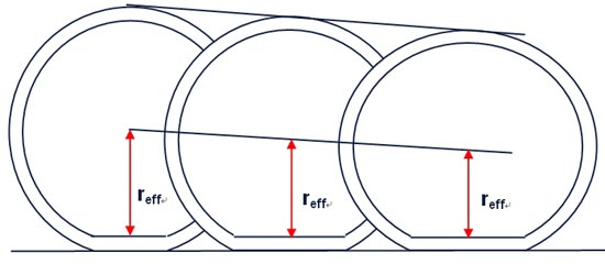
Figure 1: Monitoring principle of indirect TPMS
Scenario 2: Mainstream (low/mid-end) TPMS - direct system
Driven by US legislation, the market share of mainstream TPMS covering low/mid-end segments will exceed 50% by 2011. However, TPMS is expected to be small in Europe, Asia Pacific and Japan due to additional system costs and public awareness of TPMS. In addition, the TPMS system is usually offered as an option for high-end models, and the demand for additional equipment is still low, as the average owner is not familiar with TPMS.
The main driver of mainstream systems is price. OEMs need a system that meets the requirements of the National Highway Safety Association (NHTSA), but does not cause too much TPMS for the price of low/mid-end models. The basic functions of the mainstream system can meet the requirements of NHTSA, but the current situation is that each OEM has its own TPMS system, it is not a commodity market.
Scenario 3: High-end TPMS (automatic positioning) - direct system
High-end TPMS refers to the integration of the tire's automatic positioning function into a direct TPMS system. The automatic positioning function of the tire refers to identifying and distinguishing the information sent by the four tires. In this case, for example, the air pressure of the right front wheel can be correctly identified and displayed without any human operation.
Today's systems primarily install low frequency transmitter antennas in the wings for positioning. There are four low frequency transmitter modules that wire the central receiver module to the wing. The central receiver module sends signals to these low frequency modules to trigger a particular wheel module, such as the right front wheel. In this case, only the wheel module of the right front wheel (rather than the remaining wheel modules) will feed back the information. In the future, a two-axis G sensor will be used to achieve the automatic positioning function of the tire. It is estimated that by 2011, the market share of high-end TPMS systems will reach 30%. The system will also be the basis for future TPMS/ESP integration (see description of Scenario 4).
Scenario 4: Combination of ESP/ABS and TPMS - Direct System
The system is the future direction of development. In this system, the TPMS system provides additional information on the tires to the ESP system such as gravity, tire pressure and temperature, road conditions and tire type. This is the development trend of future advanced ESP systems. Such systems require multi-axis gravity measurement and automatic positioning, as well as battery-free systems that use low frequency or "energy harvesting" technology. This type of system will introduce high-end cars (based on low-frequency systems) for the first time in 2008. It is estimated that by 2011, its market share will reach 10%.
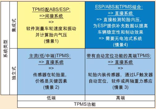
Table 1: Comparison of direct and indirect TPMS
Table 2: TPMS Type
TPMS requirements and design challenges
The requirements of the TPMS system are: low power consumption, high operational reliability in harsh environments, low pressure sensor error tolerance, and longer operating life. To achieve the 10-year lifespan goal, low-power integrated components must be used. Power management is therefore a top priority.
When designing a system that is stable and efficient, the first factor to consider is software. Because wheel modules typically use microcontrollers to execute commands, an intelligent algorithm should be used to achieve the desired power. For example, do you have to transfer a complete 8-bit parameter to the receiver each time? Or is it more efficient to transmit a 1-bit parameter low-voltage alarm signal? How often do you measure the tire pressure? Does the system always measure all parameters, or does it measure more than one parameter for more than one parameter? Should the wheel module perform parameter calculations or receivers to perform? Software engineers must consider these issues when designing a TPMS system.
Second, the use of low frequency functions is a very effective way to control TPMS. When using the low frequency interface, the sensing module can always be in power off mode, which minimizes power consumption. The sensor performs measurement and data transmission only after receiving the wake-up signal. In addition to reducing power consumption, the low frequency interface offers design flexibility and other advantages. For example, low frequency communication allows the system to send specific commands to the microcontroller via the low frequency interface to recalibrate and position the tire.
A third way to reduce power consumption is to use a rolling switch to detect if the tire is stationary or operational. Therefore, the operation can be performed in such a way that the corresponding detection and/or transmission takes place only when the vehicle is running.
Some TPMS sensors (such as the SP30) integrate an accelerometer, which is a high G sensor that detects wheel rotation. Therefore, the application software can be written in such a way that when the accelerometer reading is below a certain level, it indicates that the vehicle is stationary or driving very slowly, at which point the TPMS can be stopped or at a very low frequency. run. The average time a typical vehicle travels on a highway is approximately 15%. With this in mind, this design can significantly reduce the power consumption of the TPMS.
Finally, by selecting low-power components and by using components with integrated functionality to minimize component count, higher power efficiency and lower total system cost can be achieved.
A very important aspect of TPMS system design is the media compatibility of the sensor. The accuracy and reliability of the sensor are largely influenced by external media such as moisture, dust and other substances such as brake fluid. Infineon's TPMS sensor SP30 is a sandwich process consisting of a single silicon crystal sandwiched between two glass layers. The sensor element has excellent media compatibility because its air pressure inlet faces the back of the silicon diaphragm. At the same time, the way the chip is packaged will also affect the performance of the sensor.
Infineon's SP30 TPMS sensor has been in volume production a few years ago and has sold millions of units to date. As the market continues to demand higher levels of integration and lower system costs, Infineon will introduce the next generation SP35 to the Asia Pacific market in 2007. The SP35 will integrate the sensing and launch functions required for the wheel module. This means that the MCU, sensor and RF transmitter are all packaged together. The SP35 system solution will reduce one component compared to the existing SP30 plus external RF transmitter integrated circuit (IC) solution.
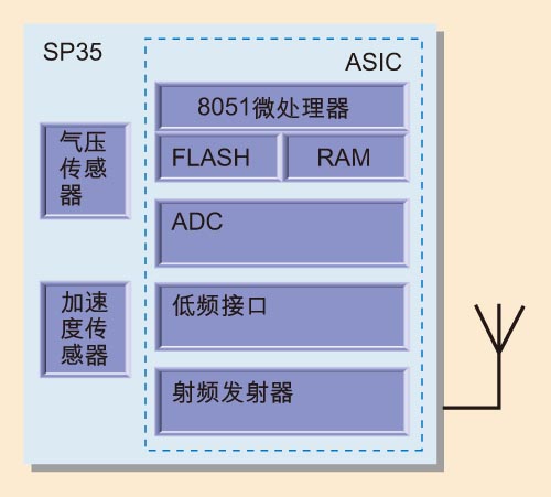
Figure 2: Infineon's next-generation TPMS sensor SP35 block diagram
The SP35 integrates a pressure sensor, accelerometer, temperature sensor, an 8051 microprocessor with on-chip flash memory, a low frequency receiver interface, and a 315/433/868/915MHz RF transmitter. In addition to reducing the number of components, it also reduces overall system cost because the board design is simpler and smaller.
Another important design challenge comes from wireless control. The first generation of TPMS transmitters were designed using the ASK modulation technique of the SAW resonator to generate the appropriate transmit frequency. Although the ASK system is very inexpensive, it is susceptible to variations in the received field strength caused by the rotation of the wheel on which the transmitter is mounted. For this reason, today's TPMS uses a crystal oscillator-based FSK modulation method and a PLL synthesizer to generate center frequency and frequency pull. In many OEM applications, the FSK has reliable RF communication capabilities, even when the wheels are spinning at high speeds.
Infineon's ultra-high frequency (UHF) transmitter TDK51xxF series are designed for use in the 315MHz, 434MHz, 868MHz and 915MHz bands, and support both ASK modulation and FSK modulation. The product family features a fully integrated phase-locked loop (PLL) synthesizer and a high-efficiency power amplifier to drive the loop antenna. With a typical power consumption of 7mA (when the resistance is 50Ohm and the RF output power is 5dBm), the device can operate over the automotive operating temperature range of -40°C to +125°C.
Infineon also offers a wide range of receiver chips for different frequency bands, integrating various functions so that system designers can use the fewest components to reduce system cost. In the FSK modulation mode, when the receiving frequency is 434MHz, the operating current is as low as 3.9-7.5mA, and the sensitivity is as high as -100dBm. (Measurement conditions: FSK frequency offset is +/- 50 kHz, bit error rate is 2xE-3 bit error rate, Manchester coding mode, data rate is 4 KHz, IF bandwidth is 280 KHz).
Wireless control design considerations
The following factors need to be considered when using the Infineon TDK51xxF transmitter:
(1). Antenna selection and matching network. Simulations and tests have demonstrated that loop antennas are more efficient and have a wider bandwidth than conventional grounded antennas. Loop antennas are typically printed on the board and properly matched for optimum efficiency. However, there are several common external factors that affect the performance and impedance of the antenna, such as the hand effect, which changes the free space (?0) and the dielectric constant near the metal object, and these factors are used to obtain accurate measurements. It is essential and must be taken into account. This proved to be a major challenge for TPMS system designers, as the antenna must be measured with as many real-time influencing factors as possible, that is, both the antenna resistor mesh and the bezel mounted on or near the bottom. Transmitter module.
(2). Power mode. In the power off mode, the entire chip is not powered, and the current consumption is typically 0.3nA. The PLL activation mode can be entered by switching FSKDTA to HIGH (because PWDWN is not connected). During this time, the PLL is powered up, but the power amplifier is turned off to avoid unnecessary power radiation when the PLL needs to stabilize.
Power mode example for FSK modulation using FSKDTA and ASKDTA (no PDWN connection)
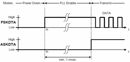
Figure 3: Example of power mode for FSK modulation with FSKDTA and ASKDTA (no PDWN connection)
The on-time of the PLL is mainly determined by the on-time of the crystal oscillator. When the specified crystal is used, the on-time is less than 1 msec. The PLL itself requires a time lock of approximately 10?s. Current consumption is typically 3.5 mA during PLL enable. The power amplifier on the TDK51xxF is switched from the ASKDTA to the HIGH position. During this time, FSKDTA can send. When a suitable transform network is applied to PAOUT, the current consumption of the integrated circuit is typically 7 mA.
(3). Crystal part. The transmitter crystal plate should be shielded and grounded and away from the antenna to avoid interference from the power output. By the same principle, the transmit clock output should be kept away from the crystal input and all crystal trace lengths should be as short as possible.
(4). The board is grounded. It is important to make a firm ground underneath the circuit. The RF and integrated circuit (IC) ground should be separated from each other.
(5). Matching component placement. All matching components should be placed as orthogonal to each other as possible on the ground plane, and if possible, their parallel matching components should be separated from each other.
(6). Antenna design part. The antenna should always be placed in "free space" (no AC power ground) and should be at least 5 mm from the ground plane. If a loop antenna is used, a symmetrical design must be made.
(7). Decoupling capacitor arrangement. The decoupling capacitor must be as close as possible to Vs and ground.
Infineon's TDA52xx is a single-chip receiver designed for short-range remote control. The basic structure of the Superheterodyne Receiver (SHR) consists of a low noise amplifier (LNA) and a front-end mixer. The IC is highly integrated and requires very few external components. The device includes a low noise amplifier (LAN), double balanced mixer, fully integrated voltage controlled oscillator (VCO), PLL synthesizer, crystal oscillator, limiter with RSSI generator, PLL FSK demodulator , data filters, data comparators (dividers) and peak detectors. In addition, the device features a power-down feature to extend battery life. The following factors need to be considered when using the Infineon TDA52xx receiver.
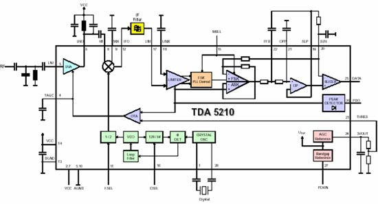
Figure 3: Block diagram of Infineon's TDA5210 Ultra High Frequency (UHF) Receiver
(1). Use SAW filter to overcome external interference. To increase the selectivity and image rejection ratio, a SAW front-end filter can be placed between the antenna and the LAN inlet. This effectively overcomes the problem of occlusion of the receiver caused by out-of-band interference signals. The power of the narrow-band front-end SAW filter must match the antenna on the input side and the LNA on the output side to achieve a flat passband, low insertion loss, and good rejection. All PCB traces should be as short as possible to minimize parasitic effects. In general, the values ​​of the input and output matching components recommended by the SAW filter vendor can serve as a good reference guide.
(2). Improve the sensitivity of the receiver. There are many factors that can affect the sensitivity of the receiver, and we can adjust each factor to optimize the sensitivity of the receiver. For better sensitivity and receiver performance, fine-tuning is required from front-end matching, LNA/Mixer circuits, IF filters and crystal frequencies, to data filters and data splitters.
in conclusion
The current protagonist of the TPMS market is a direct system using batteries. The battery-free direct system may be launched in 2008 with the ESP system for high-end vehicles. It is estimated that by 2011, the sales volume of this system will reach 169 million sets, and the average annual growth rate will reach 29% within the next five years. The right choice of components, power management, media compatibility, system cost, and RF design are all major design challenges engineers need to overcome when designing a direct TPMS. These factors are critical to business success.
Solar road light is a crystalline silicon solar battery power supply, valve control type sealed and maintenance-free battery, gel battery) to store electrical energy, super bright LED as light source, lamps and lanterns and controlled by the intelligent charging and discharging controller, is used to instead of the traditional public power lighting lamps.

Solar road light working principle
1. Using the microcomputer intellective controller to transfer the light energy to electrical energy.Easy to install since to wiring and trenching,energy conservation and environmental protection.
2. The microcomputer intellective controller is composed by advanced special-purpose integrated circuit,high conversion efficiency,prevent over-load and over-discharge,Output short circuit protection,extend work life,on the safe side,convenient usage.
3. High effective Non-maintaining accumulator cell,strong storage,durable usage.
4. Automatic track type time controller,Automatically adjust the working time along with different illumination time in various seasons.For extending the work time energy conservation intellective controller with automatic shut-off the light at Deep-night.

Solar Street Light ,Solar Street Light Pole,Solar Street Light Battery,Solar Street Light Advantages
Jiangsu chengxu Electric Group Co., Ltd , https://www.satislighting.com