
Introduction
This article refers to the address: http://
With the development of social economy, automobiles have become an indispensable means of transportation for people's work and life. In the current automotive industry, various electronic control systems have been developed for safety, comfort, convenience, low pollution, and low cost. This paper designs an intelligent vehicle system based on ARM9 S3C2410A, which can realize vehicle positioning and data communication between vehicle and control center through GPS global positioning system and GPRS wireless communication technology. The CAN bus control module is built to collect the main part of the vehicle. The working state, real-time monitoring of the main technical parameters of the car, and display comprehensive information of the vehicle information through the LCD module.
1 Intelligent car system function
The vehicle intelligent navigation terminal should have the following functions:
Vehicle positioning refers to obtaining the current location of the vehicle through the GPS global positioning system, including information such as longitude, latitude, motion speed, standard time and altitude;
Network communication uses GPRS wireless communication technology to keep in touch with the monitoring center, obtain road traffic conditions in real time, and provide a basis for intelligent management of traffic roads;
Fault detection It detects the main technical parameters of the car in real time through the CAN bus;
The information shows that it displays the vehicle position, scheduling information and detected vehicle technical parameters via the LCD screen.
The intelligent vehicle system can realize other functions according to user needs, such as adding automatic alarm function through GPRS automatic alarm, expanding audio equipment and IDE interface equipment to increase entertainment functions, connecting image acquisition equipment through USB interface, and performing video surveillance on and off the inside and outside of the vehicle.
2 Intelligent vehicle hardware system design
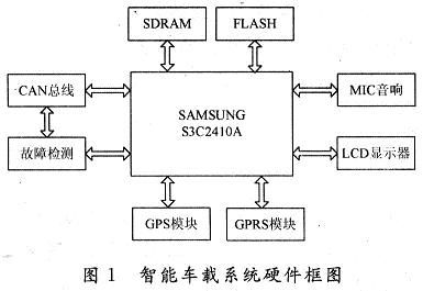
The system uses S3C2410A as the main control module, and expands 64 MBNand Flash for storing startup code and embedded Linux operating system; 64 MB SDRAM is used as memory during system operation; LCD provides better human-computer interaction interface. And connected to the GPS module through the serial port, connected to the GPRS module through the UART asynchronous serial port, connected to the CAN bus through the SPI interface, using the CAN bus to mount the sensor, detecting the main technical parameters of the car, the system block diagram is shown in Figure 1.
2.1 main control module
The S3C2410A is a 16/32-bit RISC embedded microprocessor based on the ARM920T core designed by Samsung Samsung for handheld devices and high price/performance ratio, low power consumption and low price. It uses a 5-stage pipeline and is rich in resources; it has a separate 16 KB instruction cache and 16 KB data cache, 64 MB SDRAM, 64 MB NandFLAsH, LCD controller, RAM controller, NAND memory controller, 3-way UART, 4 channels of DMA, 4 channels of PWM with timer, parallel I/O port, 8 channels of 10-bit ADC, Touch Screen interface, I2C interface, I2S interface, 2 USB interface controllers, 2 channels of SPI, the highest operating frequency 203 MHz.
2.2 GPS module
The GPS module mainly completes the reception and processing of GPS positioning information. According to the requirements of design performance and saving system cost, GARMIN's GPS25-LVC receiver is selected, which has built-in GPS25OEM board. The interface between the receiver and the main control module adopts the RS 232-compatible TTL serial port mode, so it is connected to the serial port 1 of the S3C2410A in the design. The signal line between the GPS-25LVC and the S3C2410A only needs to be connected to the TXD1 of the GPS25-LVC and the TXD1 of the S3C2410A. In addition, connect the ground wire and power cable of the GPS25-LVC to the ground wire of the main control board and the 5 V power supply.
2.3 GPRS module
The GPRS module mainly completes the communication between the vehicle and the vehicle, the vehicle and the control center. In this system, the GPRS module uses MC35. The data input/output interface of the MC35 is actually a UART that can be directly connected to the UART interface in the S3C2410.
2.4 CAN bus module
The CAN bus module allows the system to be connected to other onboard modules to complete the collection of vehicle status information and further control. The CAN bus module mainly includes the CAN bus controller and transceiver. The MCP2510 from Microchip and the PCA82C250 from Philips are used here. Among them, the CAN bus controller MCP2510 implements the CAN bus protocol, and the CAN bus transceiver PCA82C250 provides the interface between the protocol controller and the physical transmission line. Since the CAN bus controller MCP2510 has an SPI interface, it is connected to the SPI0 of the S3C2410A in the system.
2.5 Fault Detection Module
The fault detection module mainly detects the main technical parameters of the car and displays it on the LCD display. If a fault is detected, an alarm signal is issued. The main technical parameters tested in this paper include fuel consumption, braking force, steering force, engine temperature, coolant temperature, headlamps, and interior noise and exhaust. The module mainly converts various signals into electrical signals through various sensors, and then uses the signal processing circuit to perform corresponding processing on the electrical signals, so that it can perform data transmission with the CAN bus module.
2.6 LCD module
The LCD module is used to display information and provide a good human-computer interaction interface. The processor S3C2410 of the main control module of this system has built-in LCD controller and supports STN-LCD and TFT-LCD. This article selects Sharp's TFT-LCD module LQ080V3DG01, which has a resolution of 640 × 480, 18-bit color depth, and can be directly connected to the LCD interface of S3C2410A.
3 Intelligent vehicle system software design
Because Linux has many advantages such as open source code, convenient tailoring, and convenient porting, the system chooses embedded Linux as the software running platform. Embedded Linux is to port the Linux kernel to the S3C2410A platform. The embedded Linux operating system not only makes software development more flexible, but also improves the reliability of the entire system. The specific process of the software design is shown in Figure 2.
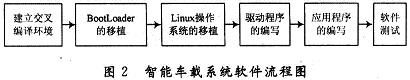
The cross-compiler environment is a comprehensive development environment consisting of compilers, connectors, and interpreters. BootLoader is the first piece of software code that starts and runs the system, similar to the BIOS of the PC plus the bootloader in the hard disk MBR. It can initialize the hardware device and establish a map of the memory space to bring the system's hardware and software environment to a suitable state, and prepare a suitable environment for the final call of the operating system kernel or user application. The migration of the Linux operating system is to re-cut, compile and transfer the Linux kernel to the S3C2410A. The following is a description of each module driver and application programming.
3.1 GPS positioning function realization
The basic idea of ​​GPS module software design is as follows: First, receive the complete NMEA0183 statement, and then extract relevant data (time, latitude, longitude, speed), then send the data to display or send it, and save it for later viewing.
Since the GPS module communicates with the S3C2410A through the serial port 1, this paper designs the corresponding serial port communication program under the Linux system. The specific steps of the serial program design are as follows:
(1) Initialization of serial port 1: Set the communication mode of serial port 1 to 8-bit data bit, 1-bit stop bit, and no parity bit. The baud rate is 4 800 b/s.
(2) Receive ASCII code character information one frame at a time.
(3) Perform data processing on each frame of ASCII code character information.
In the data processing process, the following serial communication ideas are designed for the required positioning information requirements:
1 Receive the positioning statement with "$GPRMC" as the filter condition.
2 The 59 characters after "$GPRMc" are useful information, so "59" is used as the basis for judging the complete positioning statement.
3 In the process of data reception, there are often two situations. One is that each frame will get a complete statement starting with “$GPRMCâ€, and the other is that the second half of the previous frame is added before the next frame. Part of the complete positioning statement that is composed together.
3.2 GPRS communication module implementation
The GPRS module realizes the wireless transmission of data by means of the GPRS wireless network, thereby establishing a bridge of communication between different vehicles or vehicles and the control center, so the function of the software is mainly to establish a wireless connection and transmit data according to the GPRS communication protocol.
The communication of the GPRS module is mainly realized by the serial port driver. The support of the serial device has been provided in the embedded Linux kernel. Therefore, when configuring the kernel compile option, only the support of the serial device is selected, and the GPRS module can be realized. Serial data communication function. In order to communicate with the Internet, you also need to select the PPP and TCP/IP protocols when configuring the kernel compilation options. In this way, once the network connection is established, the application can be used to communicate network data.
The data link layer of the system adopts the PPP protocol, which is a character-oriented protocol designed for transmitting data packet connections between two peer entities, using the scalable link control protocol LCP to establish, configure and Test the data link. The network control protocol family NCP is used to establish and configure different network layer protocols and to allow for multiple network layer protocols. A PPP session is divided into four steps: establishing a connection, connection quality control, network layer protocol configuration, and connection termination.
The embedded Linux system kernel is derived from the Linux kernel and retains support for TCP/IP and other network protocols. Writing a web application on an embedded Linux system is no different than writing a web application on Linux. It can usually be ported to an embedded Linux system with minimal modifications. At this point, the GPRS module is fully integrated into the embedded terminal.
3.3 CAN module implementation
The tasks of sending and receiving messages to be completed by the CAN bus driver are all around the CAN bus controller. Therefore, the driver mainly operates the internal registers of the controller MCP2510. The initialization of the CAN bus controller MCP2510 follows the following steps:
(1) Software reset, enter configuration mode;
(2) setting the CAN bus baud rate;
(3) Turn off the interrupt and set the ID filter;
(4) Switch the MCP2510 to the normal state;
(5) Clear the receive and send buffers;
(6) Turn on the receive buffer and turn on the interrupt.
4 Conclusion
The system can not only realize the vehicle positioning and the data communication between the vehicle and the control center through GPS and GPRs, but also can detect the main technical parameters of the car through the CAN bus, which provides a reliable guarantee for the intelligent management of the traffic road and the safe driving of the vehicle.

Led Grow Light,Ultrathin Led Grow Light,Led Grow Strip Light,Rgb Led Grow Light
Shenzhen Mingxue Optoelectronics CO.,Ltd , https://www.mingxueled.com