
Each mobile station is an interference signal source for users in the same cell and adjacent cells, so good transmit power control is important to improve the communication performance and capacity of the CDMA system. The closed-loop power control method in the CDMA system introduced in this paper can effectively control the power of the mobile station. The article also introduces the practical application of the high-precision RF power detector LMV225 for power control.
This article refers to the address: http://
Since the commercialization of the CDMAIS-95 cellular network in 1996, CDMA technology has proven to be the best wireless technology to advance the development of the cellular personal communication industry. According to the CDMA Development Group (CDG) report, CDMA subscribers grew by 24 million in the first six months of 2004, and the total number of users worldwide reached 212.5 million. All mainstream third-generation standards, such as CDMA2000, W-CDMA, and TD-SCDMA, use CDMA as the access method. CDMA is based on spread-spectrum modulation technology, and the principle of spread spectrum is based on Shannon's information theory. Shannon’s capacity law states that the channel capacity in additive white Gaussian noise is:
![]()
Where: Csh is the channel transmission capacity, the unit is bps; BRF is the channel bandwidth, the unit is Hz; SNR is the signal to noise ratio.
To achieve the same capacity of Csh compared to a narrowband system (ie, a smaller BRF), the wideband system (ie, larger BRF) requires a lower signal to noise ratio SNR. On the other hand, in a channel of a given bandwidth BRF, a higher SNR has a larger transmission capacity. This means that if all users transmit the same amount of data, the same channel can have more users.
The importance of power control in the CDMA reverse link
Since any mobile station can be regarded as a source of interference to other users in the same base station coverage area and neighboring cellular handset users, the transmission power control of the mobile station is very important for CDMA operation performance and system capacity. Therefore, the more mobile stations in the running state, the greater the interference within the system; the lower the mobile station's transmitting energy, the lower the total interference. That is to say, the higher the SNR in the RF carrier bandwidth BRF, the larger the system capacity Csh.
The power control scheme mainly sets the transmitting energy of the mobile station to the lowest level, so that the base station can receive signals of similar power levels from each mobile station. Under this condition, the signal-to-noise ratio at the input of the base station is: SNR=1/(M-1), where M is the total number of users of the base station.
Taken together, the main benefits of implementing power control in a CDMA system are:
1. Increase system capacity
2. Minimize the Near-Fare effect
3. Reduce the power consumption of the mobile station
IS-95 and CDMA2000 power control for mobile stations or access terminals
Power control is characterized by controlling the level of interfering signals in the reverse link by estimating the optimal transmit energy level and responding to power control indications sent by the network or base station.
In CDMA IS-95 and CDMA2000 1X, the base station determines power control; while in CDMA2000 EV-DO, the access terminal performs power control. The two standard power control schemes are similar, using two power control methods, open loop control and closed loop control.
Open loop power control
The open loop method uses the power level PRX of the mobile station receiver to estimate the forward link loss, and then specifies the initial transmit power PTX of the mobile station, such that based on different user terminal selections (eg, cellular, PCS, or 3G), forward and The sum of the powers of the reverse link is kept constant, that is, PTX+PRX is constant. PRX is calculated by Eb/Io, which is measured by the mobile station's digital signal processor (DSP).
After the initial PTX is obtained, both the mobile station and the base station start closed loop control. In accordance with the CDMA standard being implemented, the base station sends an error signal to the mobile station instructing the mobile station to increase or decrease the energy of one unit.
2. Closed loop power control
Closed-loop power control consists of two steps: the outer loop (only for the base station) and the inner loop (the mobile station and the base station simultaneously), and the closed-loop control in IS-95 and CDMA 1X can achieve a power control rate of 800 Hz.
The main purpose of closed-loop power control is to minimize the fast attenuation effect caused by signal multipath propagation loss based on the measurement results of the base station. Combined with the closed loop power control process of the outer loop and the inner loop, the attenuation compensation of 20 to 35 dB can be achieved in the interframe interval of 20 milliseconds, and the dynamic range can reach 80 dB.
a. Outer loop closed loop power control
In the outer loop, the base station specifies a target Eb/Io (from the mobile station to the base station) for each frame of the receiver every 20 milliseconds. When a frame error occurs, the Eb/Io value is automatically reduced by 0.2 to 0.3, or increased to 3 to 5 dB.
The closed loop control step of the entire outer loop is only related to the base station, and is independent of the mobile station.
b. Inner loop closed loop power control
In the inner loop, the base station compares the Eb/Io and the target Eb/Io of the reverse channel every 1.25 milliseconds, and then instructs the mobile station to reduce or increase the transmit power, so that the target Eb/Io can be achieved. For CDMA2000, the power variation amplitude is between ±0.25dB and ±0.5dB, while for CDMA IS-95, the power variation is ±1.0dB. The corrected rate is 800 bps.
Hardware Implementation of Power Control in CDMA Mobile Station
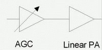
In summary, CDMA IS-95 requires the mobile station to adjust the transmit power by ±1.0 dB every 1.25 milliseconds, while CDMA2000 can be ±0.25 dB to ±0.5 dB. Figure 1 shows the general output power control of a linear power amplifier signal chain for a handheld device. Since CDMA requires high linearity, the output power amplifier is typically biased at a fixed gain, which must then be adjusted by a gain-controlled linear driver amplifier, which is commonly referred to as automatic gain control in CDMA mobile stations. (AGC) amplifier.
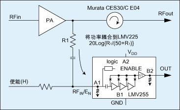
The experiment found that the RF transmit structure in Figure 2 can reduce the DC power consumption of the power amplifier due to the use of isolators (such as Murata CE04 and CES30) and the high-precision RF power detector LMV225. The isolator provides a near-perfect 50 ohm load for the output of the power amplifier, while the LMV225 is capable of detecting accurate transmit power levels. The DSP of the mobile station then sets the output power to the level required by the base station. In this application circuit, a resistor is used to transfer the RF signal of the main signal channel to the input of the LMV225. In addition, a capacitor of approximately 100 pF is required for blocking to prevent the enable control signal from entering the main signal path. This DC blocking capacitor is necessary because it does not want DC voltage to enter the output of the power amplifier or the isolator. Since there is already an isolator, most of the transferred RF energy comes from the transmit power amplifier. The reflected energy from the antenna will be transferred to the isolator's built-in 50 ohm load, rarely reaching the output of the power amplifier or the LMV225. Therefore, the power coupled to the LMV 225 can be estimated using 20log [R1/(R1+50)].
The actual test results show that the power amplifier with a power supply current of 500 mA and an adjacent channel power rejection (ACPR) of -40 dBc can be improved to a power supply current of 450 mA and an adjacent power supply rejection of -50 dBc. In this case, the current is reduced by 10% and the distortion is improved by about 10 dB.
We have now demonstrated that for the IS-95, W-CDMA, CDMA2000, and TD-SCDMA air interfaces, the LMV225 and a CES30 isolator can perform better in terms of power consumption and RF distortion in linear CDMA power amplifier applications. performance. In fact, due to the uncertainty and variation of the device in the transmit signal path (like AGC, gain of the power amplifier, and loss of passive components, etc.), in order to achieve strict inner loop closed loop power control, CDMA2000 mobile station or access terminal It is necessary to use the LMV225 as a transmit power detector.
Mobile station transmit signal channel
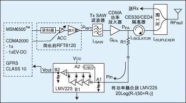
The RF transmit circuit architecture of Figure 2 can be used for a wide variety of different CDMA chipsets. Figure 3 is a simplified diagram of the LMV225 application recommended for CDMA2000 1X or EV-DO single-band handset transmit power detection. In this transmitter configuration, the power output to the antenna is:
RFout=PRFT-LSAW+GPA-LISOLATOR-LDUPLEXER
Where: RFout is the RF power to the antenna (assuming 50 (impedance load) is achieved; PRFT is the output power of the RF transmitter chip; LSAW is the insertion loss of the SAW filter; GPA is the fixed gain of the CDMA power amplifier; LISOLATOR The insertion loss of the isolator; LDUPLEXER is the insertion loss of the duplexer.
Since R1 and LMV225 already form a high-impedance parallel load for the signal path, the insertion loss of the resistor power divider formed by R1 and LMV225 is negligible. LSAW, GPA, LISOLATOR, and LDUPLEXER can be considered constant at room temperature. Then, the RF power RFout to the antenna can be adjusted by PRFT, and the PRFT is controlled by the AGC in the transmitting chip. In fact, AGC amplifiers typically support the 80 dB dynamic range required by IS-95 or CDMA2000. We also found that the output power of CDMA mobile stations during most of the working hours is medium, so the accuracy of power control is very important from the medium output power to the high output power. Improper high power levels reduce the talk time of the mobile station and cause more interference to other network users.
Advantages of LMV225
To provide the best power detection range in CDMA handsets, the LMV225 is optimized for design. As mentioned above, precise power control from medium power to high power is especially important. The coupling resistor R1 allows the LMV225 to know the critical range of RF signal occurrence. Assume that the AGC is set at the high/highest gain to achieve the maximum output of the CDMA power amplifier, such as 28 dBm. If the amplitude factor of the RF transmit signal is 3 dB at this time, the instantaneous peak power of the CDMA power amplifier will be 28 + 3 = 31 dBm. If we choose it as the maximum reference point that the LMV225 should be able to detect, that is, when the instantaneous output power of the power amplifier is 31dBm, the RFin/enable pin input to the MV225 is 0dBm, and a 31dBm coupling factor should be used. We found that using a 1.8K (R1 can produce a 31dBm coupling factor in this circuit.
Linear characteristics of LMV225
The LMV225 has a 30dB linear detection range, which reduces the complexity of the production calibration process. The calibration process is an important part of the CDMA mobile station production process. The automated test equipment is used to collect mobile station output power information from the weak to strong control code/signal, which is stored in the mobile station's memory for field use. When the base station requests output power, the DSP of the mobile station finds from the memory the control code/signal that should be used to achieve the requested output power level.
Some AGCs on the market may have exponential characteristics between the control signal and the output gain. If this AGC is used with the LMV225, the linear characteristic in dB will not be compared to other detection methods (such as diode detection). Make the original control curve more complex than the original AGC characteristic curve. However, if the AGC has a linear control range, linear features in dB will reduce the calibration point from more than 20 to about 2. The two-point calibration process is based on the following principle: In a two-dimensional plane, only two different points are needed to represent a first-order linear equation. If the equation is y=mx+b, the slope m and the intercept b can be calculated using the two test coordinates (x1, y1) and (x2, y2).
LMV225 in dual-band CDMA2000 mobile station
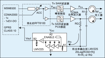
Figure 4 is a recommended block diagram for a CDMA2000 handheld device. Although the resistors R1 and R1' may not be the same, the user can optimize the performance of the two bands so that the values ​​of R1 and R1' are the same. On the other hand, since only one power amplifier is in operation in practical applications, and the resistor R1 or R1' usually provides 30+dB isolation, the isolation between the low and high bands should be within an acceptable range.
Bluetooth Headphones can be used simultaneously, also one of them can be used separately. And can connect two devices simultaneously. HD Microphone, provide clear and loud sound.Conveniently with our Built-in Microphone on earbuds with CSR chip. Noise Cancellation for safe and sound One-Touch Hands-free Calling so you don't have to stop biking, running, walking, or driving. Ould be connected as a pair or used each separately. Glad to share one for your friend or your family. Music sharing with true free.
We are the Top Chinese manufacturer of Black Bluetooth Headset , and looking forward to cooperate with you!
Color Earphones,Double Bluetooth Headset,Earphones With Charging Case,Wireless Stereo Bluetooth Earphones
ShenDaDian(China) Digital Electronics Co.,Ltd , http://www.btearbuds.com