
With the continuous expansion of wireless technology applications, the field of industrial control has begun to use wireless communication technology for on-site data transmission. Compared with wired devices, wireless communication technology has the advantages of low cost and no wiring. In recent years, ZigBee, a low-cost wireless network communication standard, has attracted much attention, and has continuously developed a wireless network communication device based on the ZigBee standard and a wireless network communication technology based on the ZigBee standard (hereinafter referred to as ZigBee technology). The ZigBee standard is based on the IEEE 802.15.4 protocol and has powerful device networking capabilities. It mainly supports three types of self-organizing wireless networks: star networks, peer-to-peer networks, and cluster tree networks. Network system nodes have multi-hop routing functions, especially capable of forming a cellular mesh network structure, and therefore have strong network robustness and system reliability.
ZigBee technology has the characteristics of low power consumption, low cost, short delay, high capacity, and no wiring. It is a core upgrade of existing vehicle detection systems, which will greatly simplify the system structure and reduce production and maintenance costs. .
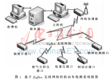
1 System overall design <br> The complete vehicle detection system is generally composed of three parts: back-end management system, front-end control system and on-site inspection system. The background management system consists of a server, an office system, a charging machine, etc. The foreground control system consists of a main control computer system, a front panel, a photoelectric switch, a network system, a recording program, and a communication service program; the on-site detection system is analyzed by CO/HC. Instrument, smoke meter, speed test bench, wheel weight meter, brake test bench, skid test bench, headlamp detector, sound level meter and secondary instrument. The block diagram of the detection system based on ZigBee wireless network is shown in Figure 1.
This article refers to the address: http://
In the detection system, a star topology is adopted, and only one network coordinator controls the communication of the entire network, mainly completing network synchronization and maintaining link management between devices. In the network, terminal devices cannot communicate directly, and communication between devices can only be completed through the network coordinator.
The detection device of each detection station in the on-site detection system has a built-in ZigBee module to become a wireless terminal node, and the network coordinator is connected to the main control machine in the foreground control system through the UART interface. When applied, the terminal device (terminal node) is connected to the field detecting device; the base station (coordinator) is connected to the foreground main control device. The terminal device part performs filtering processing calculation on the data collected in real time, and the processed data is modulated into an analog signal by the ZigBee radio frequency (RF) front end integrated in the chip CC2430. The CC2430 in the base station part demodulates the received remote data and transmits it to the host computer through the UART interface to further process, analyze, display, store and share the data. Since the equipment is placed in the field data collection point at one time, no additional wiring is required, which reduces the construction difficulty and cost. At the same time, even if a device fails, it will not affect the normal operation of other devices, which enhances the reliability and stability of the system. Because the equipment can be taken away from the on-site data collection point, the maintenance work is more convenient and quicker.
2 Terminal node and coordinator design <br> The terminal node consists of ZigBee chip CC2430, LPC2292, external memory Flash, ADC module, RS232 and RS485 interface, which is responsible for the collection, storage and wireless transmission of on-site detection data. The terminal node hardware schematic is shown in Figure 2. The CC2430 is a low-cost, low-power, single-chip, highly integrated solution based on the IEEE802.15.4 standard. It operates on the ISM free band and operates at 2.4 GHz.
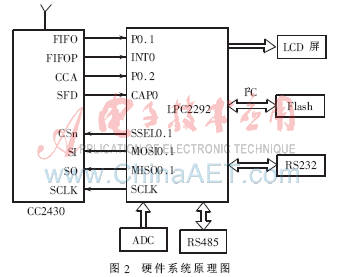
The terminal node is equivalent to a communication protocol converter, and the corresponding communication interface is set according to the interface characteristics of the connected detection devices (such as CO/HC analyzer, smoke meter, speed test bench, wheel weight meter, brake test bench, etc.). (RS485, RS232 and A/D sampling interface), direct data acquisition and analysis. The main module of the control module is the LPC2292 of the ARM7TDMI-S core. The maximum operating frequency is 60 MHz, which contains 256 KB of flash space and 16 KB of RAM space. The peripheral control part includes timer module, capture/compare module, and A/D conversion. The module, SPI interface and USART serial port complete the control and processing functions of the system.
The CC2430 is connected to the main controller via SPI, where the main controller is in master mode and the CC2430 is in slave mode. The LPC2292 also has four I/Os connected to the CC2430. The main function is to query the status of the CC2430 when necessary. The CC2430 uses four pins, SFD, FIFO, FIFOP, and CCA, to indicate the status of data to be transmitted and received. The high level of the SFD pin indicates that it is in the receiving state; the FIFO and FIFOP pins indicate the state of the receiving FIFO buffer; the CCA pin outputs a high level when the channel has a signal, which is valid only in the receiving state. The CC2430 is a half-duplex RF chip that is only in one working state at the same time. The CC2430 has 15 command registers, each with a fixed address. The transmit buffer is separate from the receive buffer: the TXFIFO and the RXFIFO are each 128 bits.
The hardware structure of the coordinator is similar to that of the terminal node, and will not be described here. The format of data transmission is as shown in Table 1. The frame data format is: detection station number (1B) + data content (4B).
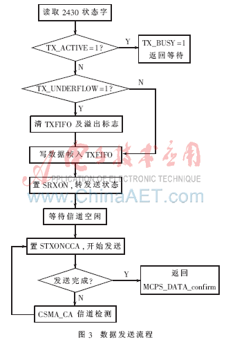
2.1 Hardware Data Transmitter <br> The Transmitter first checks the status word to ensure that the CC2430 allows transmission. If the transmission is allowed, the program first clears the information remaining in the TXFIFO, and then writes the data packet to be sent to the TXFIFO through the SPI. The send command is then triggered via the SPI interface, ie STROBE_ STXONCCA. The status bit is used to determine whether the transmission is successful. If it is unsuccessful, the CSMS/CA algorithm is called to try multiple times; if the transmission is successful, the primitive that sent the success is returned to the upper layer. The program flow is shown in Figure 3.
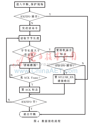
2.2 Hardware Data Receiver <br> When the CC2430 receives a valid data packet, it will indicate the arrival of the data packet by raising the FIFOP pin level. The master controller detects that the high level of FIFOP triggers an external interrupt and uses the interrupt function to receive data. This interrupt priority is set to the highest. The program flow is shown in Figure 4.
3 Network Establishment and Communication <br> The network system designed in this paper does not use the standard configuration file defined by the ZigBee Alliance, but configures the network in the application. Set the maximum number of child nodes of the node to 5, the network depth to 3, and the maximum number of routers in the child node to 3. The maximum number of nodes in the network can be calculated as 66.
In the LR-WPAN defined by the ZigBee technology, the starting point of network establishment is the PAN Coordinator. The node will establish a new PAN network in two cases: (1) no beacon frames are received during active scanning; (2) the received beacon frame parameters do not match their own node capabilities.
The steps to establish a PAN network are as follows:
(1) After the coordinator node is powered up, the NLME-NETWORK-FORMATION.request primitive is first issued by the network layer, and then the network layer management entity (NLME) requests the MAC layer to detect the network channel by issuing the MLME-SCAN.request primitive. The effective channel energy is scanned, and the result of the scan is returned to the network layer management entity by the MLME-SCAN.confirm primitive. The NLME discards the channel with the lower energy level according to the energy detection result, and then actively scans the selected channel to finally find the best channel for establishing the network (the default is 18 channels).
(2) Select the network identifier. Each network is assigned a separate network identification PAN ID. Devices in the network use this identity to identify the network they belong to. After completing the first step of the work, the coordinator node selects a random network identity on this channel and begins to listen to the channel. This system uses the PAN ID number 0x1aab corresponding to channel 18.
(3) Set the network address. Once the network identity is selected, the NLME will select a 16-bit network address and modify the PIB attribute macShortAddress of the MAC sublayer by issuing the MLME-SET. request primitive. At this point, NLME will issue a MLME START.request primitive to the MAC layer to start a new PAN operation. Then, the Network Layer Management Entity (NLME) notifies the upper layer of the execution result of the initialization ZigBee Coordinator by sending the NLME-NETWORK-FORMATION.confirm primitive.
After the ZigBee coordinator device establishes a network, the terminal device can join the network established by the coordinator as a child node. There are two ways for the child nodes to join the network: join the network through the MAC layer association mode; join the network directly through the specified parent node. This article takes the former approach.
First, the child node calls the NLME-NETWORK-DISCOVERY.request primitive to set the channel to be scanned and the time for each channel scan. Once the MAC layer completes the scan, it will send the MLME-SCAN.confirm primitive to inform the network layer, the network. The layer will send the NLME-NETWORK-DISCOVERY.confirm primitive to inform the application layer that the application layer selects the discovered network join from the association table. Once the potential parent node is determined, the network layer will call the MLME-ASSOCIATE.request primitive to the MAC layer. After receiving the network access request from the node, the coordinator's MAC layer stores the 16-bit network address assigned to the child node and its IEEE 64 bit network address into the AddressMap, and records it in the NeighborEntry. The coordinator will create an entry in the association table as its child node and return the terminal node with the 16 bit network address in the confirmation message via the MLME-ASSOCIATE.reponse primitive.
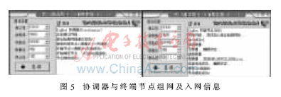
FIG. 5 is a related information display of the coordinator networking and the terminal node accessing the network. In debug mode, the hardware sends data to the computer through the serial port. The serial port transmission is set to: rate 9 600 b/s, 8 data bits, 1 start bit, 1 stop bit, no parity. The left side of Figure 5 shows the process of coordinator networking and adding child nodes, and the right side shows the process of child nodes entering the network.
ZigBee is a high-performance short-range, low-rate wireless network technology with broad application prospects. The vehicle detection system has many terminal equipments and complex on-site environment. ZigBee technology is used to construct the wireless sensor network and realize real-time processing of each inspection station data. It has simple networking, low system cost, easy expansion of network, stable communication and maintenance. The advantages of simplicity and so on are new trends in the integration and intelligence of motor vehicle detection systems.
references
[1] DANG P, LEWIS FL, POPA D O. Dynamic localization of air-ground wireless sensor networks [C]. Proceeding of the 14th Mediterranean Conference on Control and Automation, 2006.
[2] Yan Chaoyong, Hong Jialong, Liao Southwest, et al. Application Research of Vehicle Monitoring Station Monitoring and Control System[J].äº¤é€šæ ‡å‡†,2007(10).
[3] Wang Fang, Liu Yunfei, Liu Yunqing, et al. Design of Multi-function Data Collector in Motor Vehicle Detection System[J]. Instrument Technology and Sensors, 2009(7): 66-68.
[4] Zhao Wei, Yue Bingliang, Gao Dawei. Research on Network Layer of Zigbee Wireless Solution[J]. Computer Measurement & Control, 2007(5): 689-691, 694.
[5] Sun Yugeng, Zhang Jing, Sun Yongjin, et al. Wireless Ad Hoc Sensor Network[J]. Journal of Transduction Technology, 2004(2): 331-348.
[6] Ou Jiefeng. Research and implementation of wireless sensor network based on IEEE802.15.4 [D]. Hangzhou: Zhejiang University, 2006.
[7] Liu Qing, Song Lijun. Research on ZigBee Wireless Sensor Network Networking[J]. Computer Development & Applications, 2008, 21(6): 44-45, 48.
[8] DOUCET A, FREUTAS DN, GORDON N (Eds.). Sequential Monte Carlo Methods in Practice, Springer-Verlag, 2001.
[9] EUSTICE R, SINGH H, LEONARD J. Exactly sparse de layed-state filters for viewbased SLAM. IEEE Transactions on Robotics, 2006,22(6):1100-1114.
This kind is Low Noise Vacuum Cleaner. This Vacuum Cleaner is airflow control on handle and speed control on unit. It has safety valve to protect motor and double parking positions. It also has automatic cord rewinder and HEPA filter. Its suction power is very high,so you can clean clearly. This one is household vacuum cleaner. Its high suction power can help people clean the house clearly,then the environment will be better. If the air at home becomes better and better,the children will grow up more healthier. I think that's the most important,because children is the future of country.


Low Noise Vacuum Cleaner
Low Noise Vacuum Cleaner, No Noise Vacuum Cleaner, Mini Vacuum Cleaner
Ningbo ChinaClean Household Appliances Manufacture Co., Ltd. , http://www.chinaclean-elec.com