
2 Principle and structure of digital power amplifier
2.1 Principle of digital power amplifier The basic principle of digital power amplifier: use pulse signal PWM to drive high-speed power switch, wherein the low-frequency part of PWM signal contains modulation signal. This signal passes through a low-pass filter that reproduces the modulated signal (speaker). In essence, the difference from the analog analog amplifier amplifier analog signal is that the digital power amplifier directly amplifies the digital audio signal, and then performs high-precision D/A conversion, so the efficiency is as high as 85%; the fidelity is excellent, THD+N (total harmonic) Distortion + noise) is less than 0.05%.
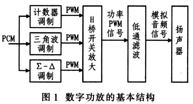
2.2 Digital Power Amplifier Structure Figure 1 shows the basic structure of a digital power amplifier. It consists of a PWM modulator, an H-bridge switching amplifier circuit, and a low-pass filter. The PWM modulator converts the input digital audio signal into a PWM signal, wherein the ∑-Δ modulation method has high precision and good stability. The H-bridge switching amplifier circuit controls the on/off of the DC power supply and uses the PWM signal current to supply power to the load. The low-pass filter filters out the switching components and smoothes the output waveform to obtain an audio signal of the analog waveform.
This article refers to the address: http://
3 TI Digital Audio Series IC Introduction Texas Instruments (TI) has long been committed to the development of digital audio products, and achieved breakthrough results. Among them, TAS55xx, TAS50xx, TAS30xx, TAS-5lxx series products are the most mature and cost-effective. The TAS55xx series is a highly integrated digital audio device with integrated PWM modulation and DSP audio processing. It has 8 channels built in, and the channel THD+N is lower than O. 05%; TAS50xx series is a high-precision audio PWM modulator with only 2 channels, channel THD+N is less than 0.01%, and fidelity is extremely high; TAS30xx series is a dedicated digital audio DSP that can achieve volume, A variety of sound effects such as subwoofer adjustment: The TAS51xx series is a dedicated audio H-bridge amplifier circuit.
4 digital audio amplifier design
4.1 Design Scheme Two design schemes are provided here. The former is TAS55xx+TAS51xx, which can get 8-channel digital power amplifier; the latter is TAS50xx+TAS30xx+TAS51xx to get 2-channel digital power amplifier. Because the latter design scheme has higher fidelity, better DSP performance, lower cost, and the devices used are easier to buy in China. The latter design scheme is described in detail below.
The actual design uses a combination of TAS5015+TAS3002+TAS5100. The TAS3002 comes with A/D and D/A converters, which enable the system to receive analog input signals and expand the range of products.
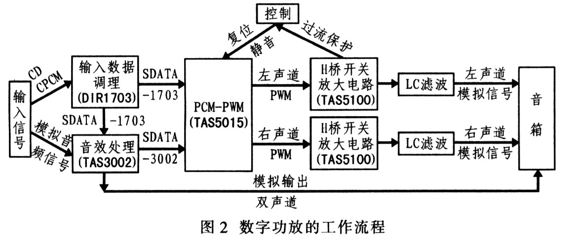
4.2 workflow digital amplifier Figure 2 shows the specific workflow, the sound source from two pathways: â‘ High-quality CD player by the obtained S / PDIF signal (a widely used high-quality stereo digital audio format provider), it After being converted by the format converter DIRl703, it enters the TAS3002; 2 the analog signal is acquired by the TAS3002 through a sound pickup device such as a microphone. The digital audio signal (represented by SDATA) in the system is processed by the DSP in the TAS3002, and then enters the PWM modulator TAS5015 and is converted into a PWM signal. Then enter the TAS5100 for power amplification, and the low-pass filter reconstructs the analog signal to drive the speaker. During the amplification process, if the circuit is abnormal, the TAS5100 can automatically send an alarm signal to reset the system, or manually reset to avoid accidents.
4.3 I2S bus TI's audio devices are connected by an I2S (Inter-IC Sound) bus. The I2S bus is a bus standard developed by Philips for the transmission of audio data between digital audio devices. The data transmission between the bus audio devices is widely used in various multimedia systems. Hardware interface specifications and digital audio data formats are specified in the I2S standard. I2S has three main signals: 1 serial clock SCLK, also called bit clock (BCLK), that is, each bit of data corresponding to digital audio, SCLK has 1 pulse. Frequency of SCLK = 2x sampling frequency × number of samples. The 2-frame clock LRCLK is used to switch the data of the left and right channels. LRCLK is “1†for the left channel is transmitting data, and “0†for the right channel is transmitting data. The frequency of LRCLK is equal to the sampling frequency. 3 Serial data SDATA Audio data represented by two's complement. Sometimes in order to make the system better synchronized, another signal MCLK, called the master clock, also called the system clock (SysClock), is 256 times or 384 times the sampling frequency.
4.4 core function module circuit
4.4.1 Digital Audio Input The digital audio input circuit is shown in Figure 3. The module mainly uses TI's digital audio interface device DIRl703 to achieve the following functions: 1 Convert digital audio signals in CD format into serial audio data recognizable by PWM modulator TAS5015, which can be transmitted directly on the I2S bus; The serial clock BCLK of the I2S bus, the frame clock LRCLK, and the system clock SCLK.
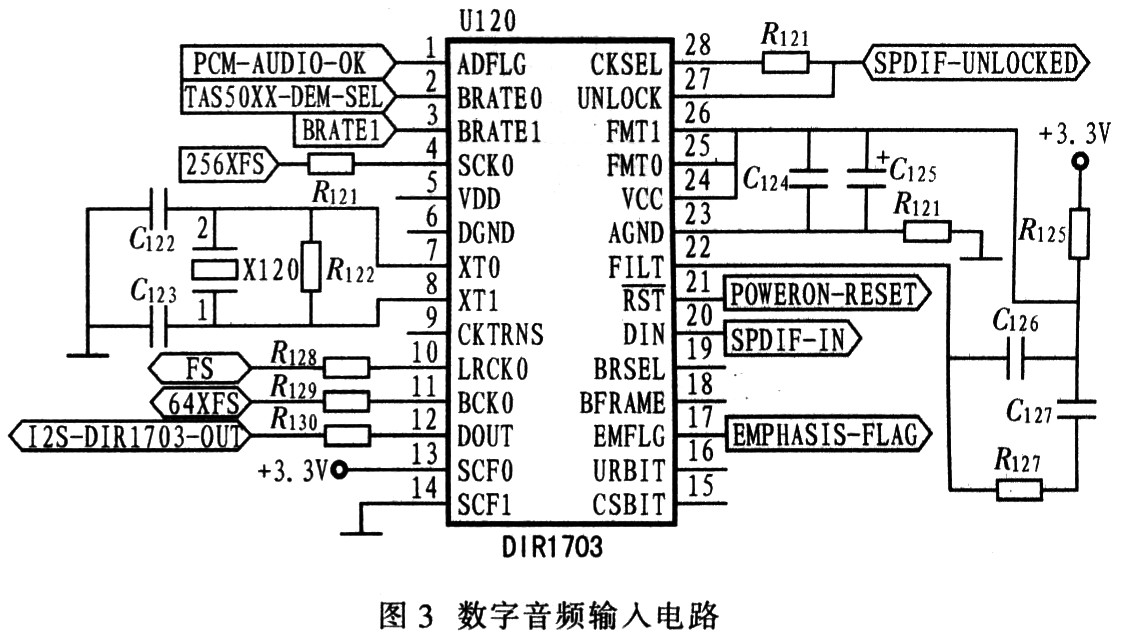
The SPDIF-IN signal input to the pin 20 of DIRl703 is the PCM signal obtained from the CD player through the optical fiber or coaxial cable; after DIRl703 processing, the SDATA signal I2S-DIR1703-OUT is output; the pins 7 and 8 of DIRl703 are connected to the external crystal oscillation. X120, while pin 4 (SCK0) outputs the system clock SCLK signal 256XFS; pin 10 (LRCK0) outputs the serial clock BCLK signal FS; pin 11 (BCK0) outputs the frame clock LRCLK signal 64XFS.
4.4.2 Digital Audio Processing Digital audio processing uses TI's digital audio processing TAS3002. The PC controls the TAS3002 through the I2C interface to obtain the desired sound. It converts the analog input signal into a digital signal input or directly receives the SDATA signal from the DIRl703 output, and digitally adjusts and equalizes the digital input signal without D/A conversion. Then, it can directly convert the processed digital signal into D/A to analog signal output to drive the speaker to sound. More importantly, it can also transmit the processed digital signal directly to the PWM modulator through the I2S bus.
As shown in Figure 4, pin 22 of TAS3002 receives the SDATA signal I2S-DIRl703-OUT of the I2S input, or directly receives the analog signal through pin 1 and pin 40, and is processed by pin 26 after digital processing by TAS3002. After the SDATA signal I2S-TAS3002 an OUT. At the same time, the processed signals of the two channels are also directly given on pins 7 and 39.
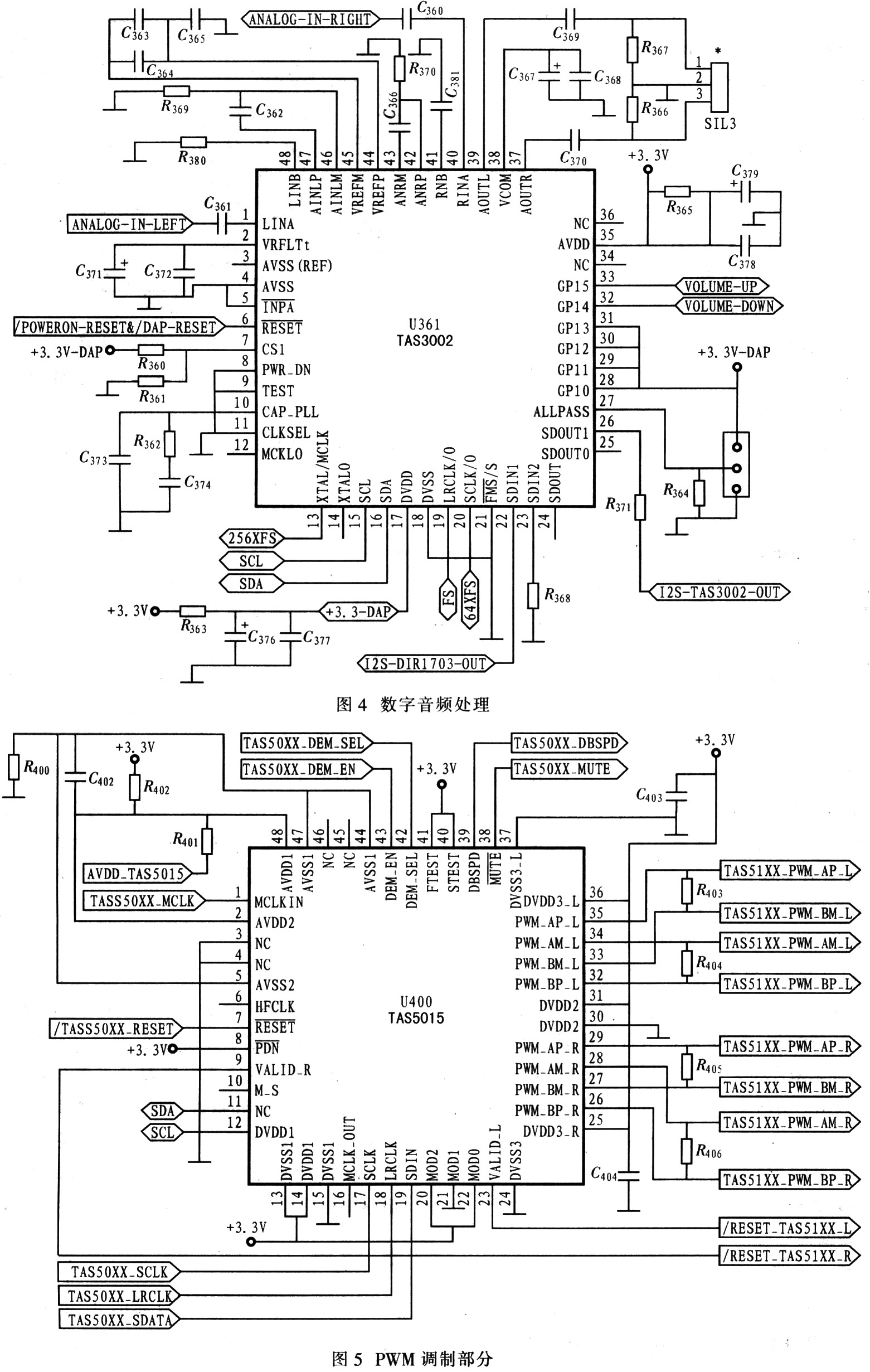
4.4.3 PWM Modulation PWM modulation is the core of digital power amplifier design. This module uses TI's TAS5015PWM modulator. It receives the digital audio signal transmitted by the DIRl703 or TAS3002 through the I2S bus, and converts it into two channels of PWM signals per channel for the next H-bridge switch amplification. It can receive external control signals for mute and reset, and adjust the sampling frequency. Its clock is synchronized with the I2S bus. As shown in Figure 5, pins 17, 18, 19 receive the SCLK, LRCLK, and SDATA signals of the I2S bus, pins 32-35 output the left channel 4 PWM signals, and pins 26-29 output the right channel 4 channels. PWM signal.
5 Conclusion In the design process, the most important issue is the synchronization problem between ICs. Since TI's digital audio ICs use I2S bus communication, the problem is solved. The digital power amplifier has been debugged with excellent results and high cost performance.
BC1 Cable Tray (H=15)
BC1 Cable Tray (H=15),Cable Raceway ,Wire Cable Tray ,Tray Cable
Cable Tray ,Steel Channel Co., Ltd. , http://www.nbcabletray.com