
Protecting electric motors used in household appliances and professional electrical equipment to prevent damage due to mechanical load overload, overheating, stall or stall, neutral line drop, severe voltage overload, humidity and other factors is a matter of great concern to equipment manufacturers. The new generation of PPTC (Polymer Polymer Positive Temperature Coefficient) self-recovery circuit protector is designed for products with AC voltages of 120V and 240V. It helps home appliance designers design safe products, prevent fires, and reduce The product is returned to the repair and replacement motor due to a motor or transformer failure.
This article refers to the address: http://
Comparison of overcurrent protection circuit protection technology
Protecting electronic circuits from damage due to current overload and overheating is a major function of many circuit protection technologies. In the past, this protection was achieved with fuses or fusible links. However, today, in systems using electric motors, self-resetting protectors, such as PPTC devices, ceramic PTC (CPTC) devices, and bimetal circuit breakers, are the preferred circuit protection schemes. In the event of a fault, these devices usually do not need to be replaced, and the circuit can be restored to normal operation after the power supply is removed and/or the source of the current overload is removed.
The protection functions of CPTC devices are automatically recoverable; however, their application may be limited due to their relatively high operating temperature, high resistance and large size. Many appliances and systems that use electric motors are often subject to shock, vibration, and thermal stress at high and low temperatures. In this case, the material of the CPTC device is often brittle and easily damaged.
Conventional bimetal circuit breakers are widely used to protect electric motors in appliances, but they cannot remain disconnected and require additional measures to prevent them from being repeatedly turned "on" and "off". Bimetals are bonded together with two different metals. When the current exceeds the rated current of the bimetal circuit breaker, the heat generated by the excessive current causes the bimetal to bend, causing a set of contacts to open and cut the current. Since no current flows into the circuit, the bimetal protector returns to normal and the contacts are turned on, so the current resumes flow. In the case of a blocked motor, the contacts of the bimetal breaker will be repeatedly opened and closed repeatedly until the power is turned off.
The bimetal circuit breaker will repeatedly open and close the contacts, which has several disadvantages. These disadvantages include material fatigue, contact damage, sparking or melting of contacts. If the contacts of the bimetal breaker cannot be disconnected, excessive current can damage the motor and sensitive electronic circuits. Bimetal circuit breakers cannot be used in advanced electronic control systems due to possible noise or "chatter" and electromagnetic interference (EMI).
Intermittent running motor protection technology
Intermittently operated motors, such as those used in agitators and food processing equipment, typically operate for a limited period of time. In general, if these products work longer than the design's highest limit, they usually cause the motor to not rotate, overheat, and eventually become damaged. Failure of the contacts or misuse by the user can result in malfunctions while the power supply is still applied to the motor.
In order to prevent overheating, the "action" of the circuit protector used must be fast, but not faster than originally intended to avoid annoying the user. The design challenge is to develop a protection plan that effectively protects the motor without nuisance.
In some mechanized devices, some electrical components have a large current at startup, and the nuisance action of the circuit protector is often associated with it. The main advantage of the PPTC circuit protector is that in order to avoid nuisance action, an action current can be specified which is much lower than the current when the motor is operating normally, but its operating time is several times the system duty cycle.
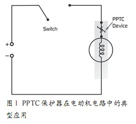
Figure 1 Typical application of PPTC protector in motor circuit
As shown in Figure 1, the PPTC protector can be installed in the circuit of the motor to protect against damage to the motor due to excessive current or overheating. If the device is mounted in a motor, it will react to the current flowing through the motor and will also react to the temperature rise, which will increase in the event of a fault.
Protection technology for continuous operation of the motor
Continuously operating motors, such as those used in refrigerators and air conditioning units, are optimized for size and cost. Because they also drive the fan, a part of the airflow will flow through the motor, so the motor can work under more heat, otherwise it is not possible. Therefore, the current when the fan motor does not rotate is generally only twice the operating current, compared to three to four times when used in other products. When the fan does not rotate, the fuse is required to be reliably blown, and when the motor is powered on, it does not blow - this is annoying. So finding a fuse like this and determining its capacity becomes complicated.
When discussing intermittent operation of the motor, we see that PTCC devices have significant advantages in protecting the motor. The weakness of the motor changes with temperature, and by changing the characteristics of the PTCC device, it can be slower—if needed.
The assembly process of production.
In the case where the motor drives the fan, it is beneficial to both the PPTC device and the motor due to the flow of air. In this way, the operating current of the PPTC device will increase significantly because of the airflow that does not reach the operating temperature. However, for whatever reason, if the fan does not rotate, there is no airflow, and the cooling effect of the airflow is lost, and the temperature of the motor rises rapidly. This condition causes the PPTC device to operate from a low resistance state to a high resistance state, thus limiting the current flowing to the motor.
Unlike single-use fuses, PPTCs prevent motor damage in the event of a fault and a slight rise in current, which can cause current overload protection and can be achieved by installing one component at a time. Overheating protection.
Application design considerations for PPTC devices
When using PPTC devices in circuits, the parameters to be considered in design are: holding current and operating current, the influence of the environment on device performance, the self-recovery time of the device, the leakage current after entering the high resistance state, and The condition for automatic recovery or manual recovery.
Hold current and operating current
Figure 2 shows the change in holding current and operating current of the PPTC protector with temperature. Area A is the action of the PPTC device, from a low-resistance state to a high-impedance state, which acts as a circuit protection current and temperature. Area B is the PPTC device current and temperature at which the circuit can be in normal operation. In region C, the PPTC device is likely to operate, enter a high resistance state, or is still in a low resistance state, depending on the resistance of the particular device and its environment.
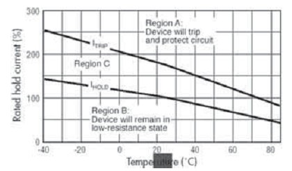
Figure 2 Maintain current and operating current as a function of temperature
Since the PPTC device will operate due to heat and enter a high resistance state, any change in temperature around the device will affect the performance of the PPTC device. As the temperature around the PPTC device rises, the energy required to bring it into the high resistance state decreases, so the holding current (I hold) drops. Ceramic PTC and polymer PTC manufacturers offer thermal derating curves and I maintain temperature-dependent changes to help designers select the right device.
Impact of environmental conditions on device performance:
The heat transfer environment of a PPTC device can significantly affect its performance. In general, the heat transfer performance of the device is increased, and the power consumption, operating time, and holding current are correspondingly increased. If the heat transfer performance of the slave device drops, the opposite is true. In addition, changing the heat capacity of the device will change its operating time.
The operating time of a PPTC device is defined as the time it takes from the occurrence of a fault current to the time the device enters a high resistance state. The action time is related to the magnitude of the fault current and the ambient temperature.
When the heat is diverging to the ambient temperature below the rate at which heat is generated, the PPTC device will operate and enter a high resistance state. If the amount of heat generated is greater than the amount of heat that is emitted to the surrounding environment, the temperature of the device will increase. The speed at which the temperature rises and the total energy required for the device to enter the high resistance state depends on the fault current and the heat transfer environment.
In normal operation, the heat generated by the device and the heat radiated to it are balanced:
I2R = U(T-TA)
Where: I = current flowing through the device, R = resistance of the device, U = total heat transfer coefficient, T = temperature of the device, TA = ambient temperature.
Whether the current increases or the ambient temperature rises, or both the current and the ambient temperature rise, the temperature of the device rises to a certain value, and its resistance rapidly increases. Due to the large change in resistance, the current in the circuit is correspondingly reduced, so that the protection circuit is not damaged.
Holding current refers to the maximum steady-state current that the device maintains a low-resistance state indefinitely and does not enter a high-resistance state from a low-resistance state. The holding current can be determined quite accurately by the heat transfer environment. The choices made during design can affect the amount of holding current, including placing the device close to a heat source, such as a transformer, which reduces holding current, power consumption, and operating time. .
Conclusion
PPTC devices have low resistance, fast transition from low-resistance to high-resistance, thin devices, and automatic recovery. These features help circuit designers design a safe, reliable product that meets regulatory requirements. Tyco Electronics' "PolySwitch" LVR devices are widely used in appliance design, comply with UL 1434 and CSA standards, can be used in televisions, comply with RoHS regulations, and can use lead-free solder and high volume
Emi Shielding Conductive Paint
EMI Shielding Silver Plated Copper Coating Paint High conductivity and excellent electromagnetic shielding performance not easy to oxidation, dried paint film with scratch resistance Consistent with ROHS and halogen-free
· Silver conductive coating paint has been specifically designed to offer increased coverage while maintaining very high conductivity. Excellent conductivity
· Very smooth, bright coating
· Meets UL specification 746-C
· Overspray easily removable with MEK
· Excellent adhesion to substrates such as polycarbonate, ABS, polystyrene and PC/ABS blends


â–·Product features
Category
Data
Units
Measure technique
Surface resistance
≤0.5
Ω/10cm
GB/T8002-6
Screening factor
72~85
dB
ASTM D4935
Adhesion
≥3B
N/CM2
ASTM D3359
Alcohol resistance
ï¹¥(50times)
50times/500g
Alcohol resistance
test
Coverage rates
4~8
m2/kg
Dry film 15um
â–·Specification
Category
Data
Units
Measure technique
Solid content
45±5
%
GB/T8005-6
Viscosity
10000~35000
cps
Stomer viscosity#2
Density
1.38±0.05
g/cm3
Dilution method
1:0.5(Alcohol)
Vol%
Mass ratio
Drying condition
65℃±5℃*30min
\
Electrothermal
constant-temperature dry box
EMI Shielding Conductive Paint
Emi Shielding Conductive Paint,Conductive Paint,Emi Shielding Conductive Coating Paint,Shielding Conductive Paint
JINAN EMI SHIELDING TECHNOLOGY CO., LTD. , http://www.emirfi.com