
There are several ways to charge a battery for a portable product. Taking a mobile phone as an example, we can use a wall adapter or other charging device to charge, this method can provide 2A, the high voltage generated by the wall adapter can reach 30V; it can also be charged through the USB cable, it can provide 500mA charging current, but the high voltage on the USB line may reach 20V; at the same time, we can also supply accessories through the mobile phone, such as external accessories such as FM transceiver. Strengthening the charging and power supply protection, making the battery more secure, longer available time, wider available voltage, shorter charging time and longer life cycle is a trend in the development of mobile devices.
DC charging channel protection (from wall adapter to battery)
This article refers to the address: http://
Figure 1 is a schematic diagram of a typical charging circuit. The charging circuit mainly has the following problems: for direct charging, charging is not protected; for reverse discharging, there is no optimized voltage drop, and there is no control inversion. Discharge current. These problems will greatly affect the safety of the system, the available time of the battery and the charging time of the battery, which is contrary to the development trend of the battery charging market, so the system protection scheme must be redesigned.
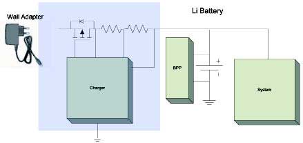
Figure 1 Schematic diagram of a typical charging circuit
We know that the protection of the system is not enough by relying on the charger itself. It is necessary to add an additional protection scheme (Box). There are two corresponding protection schemes: the first is to integrate the envisaged protection scheme into the charger IC, and the second is to use a separate external device for protection. The current trend is to use independent external components.
For direct charging, it is envisaged that the protection scheme should first solve the problem of inrush current effect, and secondly, the forward and reverse overvoltage protection should be solved. These two protection functions are necessary. In addition, it also includes over-current protection for direct charging and battery voltage monitoring. These two protection functions are optional.
Surge current effect. Due to parasitic inductance and input capacitance, the charger may generate high-voltage ringing during hot insertion, damaging the integrated circuit. At this time, we need to control the MOSFET inside the protection scheme so that the current and voltage inside the system do not exceed the rated value.
Positive and negative overvoltage protection. Due to AC-DC transients, adapter failures or errors, the output of the protection scheme cannot exceed the maximum rated voltage of the portable system. Therefore, to protect the overvoltage protection from the wall adapter, a +28V forward overvoltage protection is required. Reverse overvoltage protection of -28V. The protection device remains conductive only when the input to the overvoltage comparator is lower than the maximum rated voltage of the system.
Overcurrent protection for direct charging channels. If the direct charging channel is overcurrent, it may damage the system. However, the overcurrent protection feature should be optional, mainly because: First, the charging resistor in the charging circuit detects the charging current, and the charging current is controlled by the charging IC. Second, the output capability of the AC/DC converter is limited. If an overcurrent occurs, the voltage of the AC/DC converter will drop sharply.
Battery voltage monitoring. Up to now, the maximum voltage of lithium-ion batteries is 4.35V, and the voltage monitoring function is integrated in the battery pack. Some applications even integrate the protection scheme of two battery packs, and the charging circuit also monitors the battery voltage, so the battery voltage Monitoring can be added to the envisaged protection scheme. However, since this protection is already available in several places in the system, this feature should be optional.
In summary, it is envisaged that the protection scheme (Box) must have the following characteristics:
1. Overvoltage locking capability. The protection device should be conductive only when the bus voltage is below the maximum rated voltage of the system. If an overvoltage occurs, the protection device should be disconnected to protect the internal system.
2. With anti-overpressure capability. It is +28V when charging with a wall adapter and +20V when charging with USB.
3. Has the ability to pass current. When charging with a wall adapter, the current may reach 1A or even 2A; when charging with USB, the maximum current is 500mA.
4. Ability to control inrush current.
5. The protection device and the charging IC should be independent of each other.
If you have the above characteristics, the direct charging channel will be well protected.
Reverse supply channel (from battery to accessory)
For the reverse power supply channel, the envisaged solution (Box) must address the following issues: battery discharge, reverse overcurrent, reverse surge current, short circuit protection, and minimize the voltage circuit of the reverse circuit.
The battery is discharged. When the input voltage is lower than the battery voltage, the battery should be prevented from discharging because the accessory may not be inserted at this time. At this time, a back-to-back solution should be used to prevent battery leakage when Vin is less than Vbat. Reverse power is only supported when an accessory is detected.

Figure 2 Suggested solution
Reverse overcurrent protection. When the wrong accessory or defective accessory is connected, the battery may still discharge to the accessory, and the reverse discharge current may exceed the current passing capability of the charging channel. Since the charger cannot detect the reverse current, additional modules need to be added to detect the reverse current.
Reverse surge current suppression. When inserting an accessory, if there is no current protection scheme, it may cause a very high surge current from the battery, and may cause excessive ringing, which may damage the device. Therefore, current monitoring function must be used to control the gate of the reverse MOSFET. Thereby eliminating ringing and inrush currents.
Short circuit protection. If the accessory is directly shorted, the extremely high current from the battery may momentarily emerge, so the protection device should provide overcurrent protection, and the current can be set by an external resistor to suit different system requirements. In addition, the protection device should have an automatic recovery function, that is, when the external short circuit condition is removed, the system will automatically resume operation.
Voltage circuit from battery to external accessory. The loss between the battery and the accessory must be reduced. If the voltage circuit is too high, additional losses are generated, affecting the available voltage of the battery.
In summary, the envisaged protection scheme (Box) should have the following characteristics:
1. For battery discharge, a back-to-back structure should be used to prevent battery leakage.
2. There should be reverse overcurrent protection.
3. The reverse surge current should be controlled.
4. The short circuit of the reverse supply channel should be protected.
5. The on-resistance should be as low as possible, even if the voltage drop of the channel is as low as possible, reducing the extra losses.
Only with the above characteristics can the reverse channel be well protected.
Therefore, the architecture of our proposed solution is: back-to-back N-MOSFET, forward and reverse overvoltage protection, reverse overcurrent protection, and very low quiescent current. (figure 2)
Details of the integrated solution
Figure 3 shows a detailed block diagram of the integrated solution. By using a back-to-back N-MOS structure, the gate of the first N-MOS (identification 1) prevents surge currents from entering the system while the N -MOS also provides positive overvoltage protection.
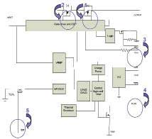
Figure 3 integrated solution
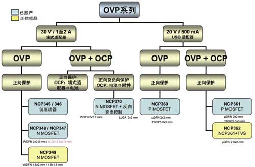
Figure 4 Ansenmei OVP product line
Another N-MOS (Identification 2) of the back-to-back N-MOS structure provides overvoltage protection of -28V. Previously used is P-MOS, but compared to P-MOS, N-MOS has lower on-resistance, enabling the battery to operate at lower voltages. At the same time, N-MOS supports a larger current, and this N-MOS also controls the current to control the inrush current of the reverse channel, providing reverse overcurrent protection.
In addition, the solution should also provide overcurrent protection (identification 3), and the current value of the overcurrent protection can be set by an external resistor. The integrated solution also provides status flag pins (identification 4) and logic control pins (identification 5) and controls the chip's operating mode.
The air defense alarm is an important component of the urban air defense system and an important combat readiness facility. The application of alarms in disaster prediction, air defense shelter, and other fields is more extensive. With the help of the alarm system, large-scale disasters can be better warned. Wartime use for civil air defense is a basic means for people's governments at all levels to implement civil air defense commands and organize personnel evacuation.

Air-Raid Sirens,Air Defense Siren Speaker,civil Defense Siren Speaker,civil Defense alarm,Civil Defense siren
Taixing Minsheng Electronic Co.,Ltd. , https://www.msloudspeaker.com