
Circuit diagram of active speakers for SOLING vehicles
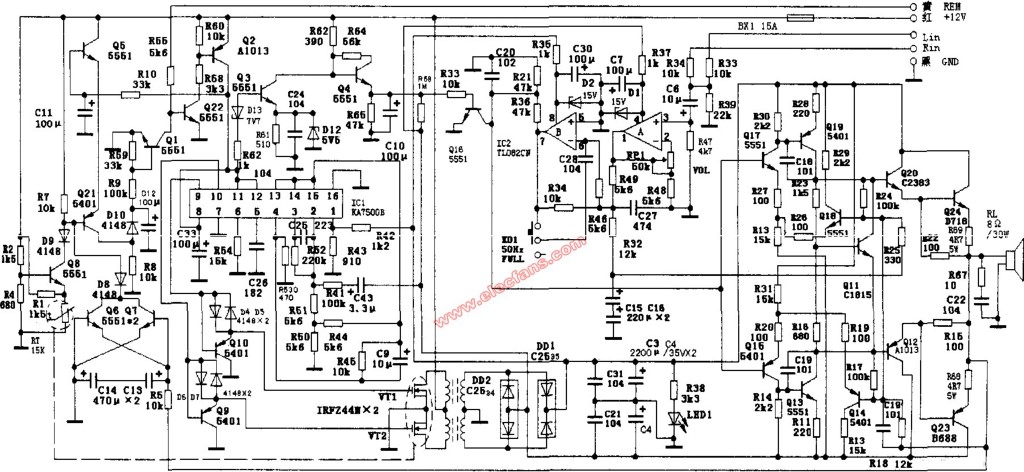
The power supply of active speakers for vehicles is taken from lead-acid batteries. Although the batteries can provide enough high current to ensure the power supply of the power output part, due to the high current power supply requirements: the wire cross-sectional area is very large, which is designed and manufactured for PCB boards. Brings a lot of difficulties. Therefore, the active speakers for vehicles are powered by DC-DC boost converter circuit, which is also the main difference between active speakers for vehicles and ordinary household power amplifiers.
(1) PWM drive and power output circuit
The power part is mainly composed of KA7500B and its peripheral components.
KA7500B forms another excited converter in this circuit, and its oscillator and drive circuit are used as the pulse signal source for driving the switch tube, so it is different from the conventional usage. The external terminal REM is the control terminal of the power switch, and it is connected to + 12V or suspended and grounded through a switch. When the speaker is required to work, REM is connected to + 12V, Q22 is turned on, Q2 is also saturated and turned on, and the ⑿ pin of ICl is powered; when the REM terminal is suspended or grounded, both Q22 and Q2 are cut off and the ⑿ pin is powered off. As long as the working voltage is supplied to the ⑿ foot, the internal oscillation circuit of KA7500B will start to work. When ⑨ and ⑩ pin output PWM pulse depends on, ④ pin voltage. In this circuit, the KA7500B ⑤, ⑥ pin is connected to a time constant circuit (C26, R54), the oscillator generates a pulse signal of about 38kHz, and two drive pulses with different timings are generated by the KA7500B internal bistable trigger control to drive two sets of drives The amplifier is finally output by ⑨ and ⑩ pins. In order to avoid that the push-pull switch tubes Q10, VT1 and Q9, VT2 are turned on at the same time, the ④ pin is connected to R53, C9, R45 to set the dead time. After a group of driving pulses turns on one arm of the push-pull circuit, another group of driving pulses are sent out only after a dead time (④ the higher the foot voltage, the longer the dead time). The continuous conduction and cut-off of VT1 and VT2 cause the secondary current of the switching transformer to induce current, which is rectified by DD2 and DD1 and filtered by C3 and C4 to provide a DC working voltage of about ± 14V to the subsequent stage. LED1 is used as a power indicator. If the light is on, it indicates that the power circuit is working properly.
(2) Overdischarge protection circuit
If the car's battery is over-discharged, it will affect its motor start. For this reason, the over-discharge protection circuit is set in the active speaker, which is mainly composed of Q3, Q4 and Q16.
When the battery voltage is normal (the normal voltage of the 12V battery is actually above 13V), the Zener diode D13 breaks down, Q3 is turned on, Q4 is turned off, and Q16 is also turned off. It does not affect the audio output of IC2⑦ feet. The power amplifier circuit has a sound source for normal jobs. When the voltage is lower than 12V, due to the clamping effect of D12, Q3 is turned off, Q4 is turned on, the base of Q16 is turned on at a high level, ⑦ pin audio output is shorted to ground, the power amplifier stage loses the sound source, and is in a state of energy saving .
2. Audio preamplifier circuit
The circuit consists of IC2 dual op amp integrated block TL082CN and related components. The input stage of TL082CN is JFET structure, which is internally connected with frequency compensation circuit and short circuit protection circuit. It has good matching performance and isolation performance between the two op amps. The conversion rate is 13V / μs, which can obtain good sound effects. The audio signals input from the external terminals Lin and Rin are first mixed through R33, R34, R39, and C6 to become a mono signal and impedance-matched, and then sent to the non-inverting input terminal of IC2, adjusting the negative feedback power of the inverting input terminal. You can adjust the gain of the op amp evenly. Therefore, use RP1 as a volume potentiometer. The signal output by op amp A is sent to op amp B through R49 and R46, and is input to the reverse input terminal ⑥. At the same time, the foot adjusts its low-frequency feedback through C28 and K01 to form attenuated negative feedback mixed tone control circuit to realize the subwoofer function. When K01 is in the floating state, it works in the full range mode. The amplified signal is sent from IC2's ⑦ foot to the power amplifier stage.
(1) Audio amplifier circuit
The machine's power amplifier stage circuit uses a typical complementary push-pull OCL amplifier circuit, using positive and negative dual power supply. Among them, Q20, Q24 and Q12 and Q23 form the power output stage of the composite tube; Q11 further stabilizes the final DC operating point; Q14 and Q18 introduce feedback signals through R18 and C19, and the dynamic compensation of the strong signal causes the operating point of Q15 and Q17 to deviate, causing output The problem of sound distortion.
(2) Speaker protection circuit
When an unexpected situation causes the midpoint voltage of the OCL output circuit to deviate from the "O" point, the DC voltage will burn the speaker. In order to avoid this situation, the machine has designed a speaker protection circuit.
When the output midpoint voltage is a positive voltage relative to the dual power supply ground, Q7 is turned on, D8 is turned on, and the base potential of Q21 is pulled down; at the same time, Q7 is turned on, so that the base voltage of Q6 is raised, Q6 is turned on, and the current is rapid Charge C19 to maintain the on-state of Q7, that is, to maintain a "steady state." Q21 is turned on, the positive potential of D10 is increased, and Q1 is saturated and turned on, Q22 is turned off, Q22 collector is at a high level, Q2 is turned off, 12 feet of IC1 are powered off, the PWM excitation pulse output is stopped, and the DC-DC conversion circuit stops working The power amplifier stage loses power, thereby protecting the speaker.
When the output midpoint voltage is negative with respect to the dual-supply ground, the emitter voltage of Q6 is lower than the base voltage, Q6 is turned on, and D8 is turned on. As a result, the above protection action also occurs, and the speaker is finally protected.
(3) Output tube overheat protection circuit
The protection circuit is mainly composed of R1, Q8 and D9. The output tube overheat protection circuit here protects both the power amplifier output tube and the DC-DC conversion output tube because they are fixed on the same heat sink as the negative temperature coefficient thermistor R1.
When the operating temperature of the power tube exceeds the normal operating temperature, the decrease in the resistance of R1 causes the voltage of the emitter of Q8 to decrease, Q8 to conduct, the negative voltage of D9 to decrease, D9 to conduct, Q2l, D10, Q1 to conduct successively, Q22 to cut off, and promote Q2 Also cut off, 12 feet of IC1 lose power, the DC-DC conversion circuit stops working, thus protecting the power output tube.
China leading manufacturers and suppliers of Brushless Dc Servo Motor,Brushless Dc Servo Motors, and we are specialize in Dc Servo Motor In Robotics,Servomotor For Vehicle Robot, etc.
Brushless Dc Servo Motor
Brushless Dc Servo Motor,Brushless Dc Servo Motors,Dc Servo Motor In Robotics,Servomotor For Vehicle Robot
Jinan Keya Electron Science And Technology Co., Ltd. , https://www.keyaservo.com