
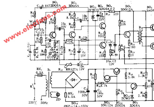
YL-3 audio electrotherapy circuit
Metal oxide semiconductor field effect (MOS) transistors can be divided into N-channel and P-channel. P-channel silicon MOS field-effect transistors have two P+ regions on the N-type silicon substrate, which are called source and The drain is not conductive between the two poles, and when a sufficient positive voltage (gate ground) is applied to the source, the surface of the N-type silicon under the gate exhibits a P-type inversion layer, which becomes a channel connecting the source and the drain. . Changing the gate voltage changes the density of the holes in the channel, thereby changing the resistance of the channel. Such a MOS Field Effect Transistor is called a P-channel enhancement type field effect transistor. If the surface of the N-type silicon substrate is free of gate voltage, the P-type inversion layer channel already exists, and the appropriate bias voltage can increase or decrease the resistance of the channel. Such a MOS field effect transistor is referred to as a P-channel depletion field effect transistor. They are collectively referred to as PMOS transistors.
P Channel Mosfet,P Channel Power Mosfet,Field Effect Transistor,Field Effect Transistor Symbol
Dongguan Agertech Technology Co., Ltd. , https://www.agertechcomponents.com