
This article talks about the hardware and software implementation of the ACC system, as well as radar functions and algorithms. The first part of it discusses the "ring-sensing system" and the FM continuous-wave (FMCM) radar system, which is the basis of the all-weather ACC system.
This article refers to the address: http://
How does the ACC system work - hardware system
The Gunn VCO is often used to generate very high frequency transmit signals. If the transmit antenna is combined with the receive antenna, the transmit signal is multiplexed with the received signal by a circulator (see Figure 1). The received signal is combined with the current transmitted signal to produce an intermediate frequency signal. Since the IF signal frequency is much lower than the transmitted signal and the received signal frequency, its sample value is very suitable for transmission to the digital processor for further processing.
Although the ACC radar sensor operates in the high frequency range (RF, RF), the signal processing for calculating the distance and relative speed is performed in the low frequency (LF). Figure 2 is a functional block diagram of the ACC system. The RF section (left) consists of the Gunn Control circuit, the Gunn oscillator, the mixer and the preamplifier; the LF section contains the analog to digital converter, signal processing and system control components, as well as the power supply and automotive network interface.
The microcontroller (Texas Instruments' TMS470R1VF76B) contains two central processors, ARM7 RISC (microprocessor, MCU) and 16-bit C54 x fixed-point digital processor (DSP), making it ideal for simultaneous control tasks and The application of high performance digital signal computing. Direct memory access (DMA) speeds up data transfer between two processors, various peripheral interfaces, and memory. The TMS470R1VF76B is fully compliant with automotive applications and is the ideal microcontroller for ACC systems. Figure 3 is a block diagram showing typical functions of a microcontroller in an ACC system application.
ACC system software
In addition to common diagnostic tasks, the ACC system performs a number of system tasks, as shown in the functional block diagram.
1. Read the default values ​​(speed, time interval) of the control parameters entered through the man-machine interface and the parameters (steering angle, wheel speed and yaw rate) detected by the sensor according to the current vehicle condition;
2. a) set the ramp parameters of the transmit frequency (start frequency, stop frequency and ramp time);
b) setting the analog to digital converter (conversion rate, number of samples);
3. Set the transmission frequency and start the Gunn oscillator;
4. Generate a transmit signal;
5. a) transmitting the transmitted signal through all antennas simultaneously, and mixing the transmitted signal with the received signal to generate an intermediate frequency signal;
b) a control loop for the control of WeChat;
6. Filtering and amplifying the intermediate frequency signal;
7. IF signal sampling;
8. Pass the sampled value to the DSP via DMA;
9. Perform digital signal processing (the first part of the frequency modulated continuous wave (FMCW) radar mission)
10. Exchange DSP calculation data;
11. Perform digital signal processing (part 2 of the FMCW radar mission)
12. Adjust speed or distance by communicating with an electronic control unit (ECU) via a car network (such as the CAN bus).
figure 1
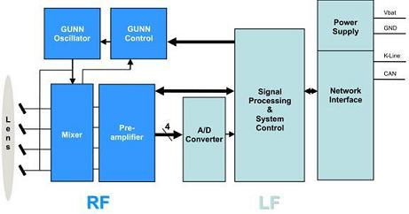
figure 2
image 3
Functional block diagram
The FMCW radar can detect targets that may affect vehicle speed and distance. As shown in the following figure, these radar tasks can be divided into two categories. The first type of spectrum analysis, peak detection and angle measurement are very large, which is more suitable for DSP execution; another type of frequency modulation, position prediction, Frequency matching, position tracking, and group filtering are relatively simple arithmetic or control functions, so it is usually the responsibility of the micro-control processor. Here is the optimization of the data stream, so the allocation of processor work is slightly different.
As shown, Robert Bosch's ACC system currently uses frequency modulation to generate three linear frequency ramps with varying ramp times.
The transmitted signal is transmitted simultaneously through four sets of antennas (A, B, C, and D). The figure below is the corresponding antenna diagram.
The received signal of each antenna is mixed with the current transmitted signal to produce an intermediate frequency signal. In this example, the system generates a total of 12 IF signals (A1, A2, A3, B1...D3) and analyzes these signals to determine the position of the target. The figure below is an example of the IF signal spectrum. In order to eliminate the noise in the spectrum, the system first sets an Adaptive Threshold for the IF signal before performing signal processing. Any frequency whose signal strength is lower than the critical value will be regarded as noise and will be filtered out. In the example above, all possible targets are marked with a red x next to them. Since the peak close to the zero frequency is generated by the reflection of the antenna mirror, it is excluded. Other frequency values ​​are used for further processing.
After the system eliminates the noise of the 12 IF signals, it uses the Fast Fourier Transform (FFT) to calculate 12 sets of spectra from the samples of these IF signals; each frequency of the spectrum represents a target detected by the system, which also corresponds to The peak signal remaining after the noise is filtered by the IF signal spectrum. We can according to the FM continuous wave radar equation,
![]()
Specify a line for each frequency of the spectrum in the speed/distance map. The figure below shows their relevance again.
To confirm that the system has detected any targets, we must use the antenna spectrum as a reference for comparison. If the lines obtained by the three frequency ramps intersect at the same point on the velocity/distance map (see the figure below), we can assume that the target has been detected by the system. However, this method sometimes gets called the ghost signal. "The false goal."
We can predict the possible location of the target based on previous calculations and mobile continuity, then use this information to check the authenticity of the frequency match and then exclude the false target. Finally, we will store the parameters of the detected target and provide them for the next calculation.
The transmitted signal is usually reflected back by multiple points on the target (eg, rear windows, trunks, wheels, etc.). This phenomenon is especially manifested in very obvious targets such as trucks, which create multiple close intersections on the speed/distance map (as shown).
If multiple sets of receiving antennas are used, in addition to the distance and relative speed, we can calculate the angle between the target and the longitudinal axis of the vehicle to confirm the relative position between the target and the car. The following figure shows the detection area of ​​an adaptive cruise control system using four sets of overlapping radio wave receiving antennas.
Using multiple sets of receive antennas causes each target to have multiple intersections on the velocity/distance map, which is similar to having multiple reflection points on the target. Below is a detailed speed/distance map obtained using two sets of receiving antennas. In order to minimize the required computational and memory space when predicting positions, we must map these probe points to the same target.
ACC System - Bosch LRR2
Many advanced cars already offer adaptive cruise control systems, or at least as an option. With the advancement of technology, the cost performance is becoming more and more attractive, the computing performance is greatly improved, and the actual device volume is becoming less and less.
Texas Instruments' TMS470R1VF76B microcontroller includes two central processing units that enable efficient operation of single-chip components. As a result, the number of parts processed by the signal is greatly reduced, and the overall system is more compact. In this way, we only need two small boards to form a complete system: one of them is the RF unit (radar sensor, Gunn voltage controlled oscillator and preamplifier); the other is the low frequency unit (power supply, DSP and Car network interface). Robert Bosch's LRR2 adaptive cruise control system reduces the size to 73 x 70 x 60 mm (internal 2.9 x 2.8 x 2.4 inches), allowing it to be mounted anywhere on the front of the vehicle.
Future adaptive cruise control systems will provide better price/performance ratios while adding more new features (such as Stop&Go and blind spot detection) and other types of sensors to enable this mid-priced car or small car to enjoy this advanced The many benefits of technology.
Three-axis Smartphone Stabilizer is composed of pan axis, rolling axis and tilt-axis. With a gyro-stabilized gimbal system, it keeps stabilized or steerable horizon with automatic calibration to give you an unprecedented smooth shooting experience.

Three-Axis Smartphone Stabilizer is born for video lovers. it stabilizers the video footage horizontally, without sacrificing the thrill of dynamic motion in the video.

Wewow focusing on handheld stabilizer is a technology company which does R & D independently. With Wenpod series product released, the company achieved the industry's praise and quickly became the leader of the smart stabilizer industry.
Our service
1. Reply to you within 24 hours.
2. Already sample: within 1-2days.
3. Shipping date: within 24 hours once get the payment.
4. 12 months warranty.
5. After-sales service, solve within 3 working dates.
If you have any questions, please contact with us directly.
Wewow appreciates domestic and international business relationship!
Three-axis Smartphone Stabilizer
Three-Axis Smartphone Stabilizer,3 Axis Handheld Gimbal For Smartphone,Smartphone Gimbal For Cell Phone,Three-Axis Stabilizer For Smartphone
GUANGZHOU WEWOW ELECTRONIC CO., LTD. , https://www.stabilizers.pl