1 Test method for light intensity distribution of lamps
1. 1 test principle of light intensity
According to the inverse square law of photometry, when the luminaire is equivalent to a point source O, the illuminance E of a certain illuminated surface ds from the space of the source R is satisfied by the following formula: I( , ) = E( , ) R 2( 1)
When the position of the illuminated surface ds is rotated to ds, as shown, the obtained illuminance is E. From equation (1), different ( , ) angles have different light intensities I, so I is along with the spatial angle ( , ) a function of change. The actual light intensity distribution is the result of this test.
1. 2 Test method for light intensity of lighting space
According to the national standards for road lighting, the coordinate system of street lamps usually uses the (C, ) coordinates shown, which correspond to medium ( , ).
The coordinates of a point M in the streetlight space can be represented by three coordinate systems (C, ), (A, ), (B, ), respectively, and their three coordinate systems can be converted to each other < 4>.
The space coordinates of the strong distribution of the road lights are tested by the luminaire distribution photometer. According to the national standards for luminaire testing, the basic types of luminaire distribution photometers are divided into three types: the first is that the luminaire rotates around two mutually perpendicular axes; the second is that the luminaire rotates around one axis; the third is the luminaire Not moving at all < 4>. Most current street light distribution photometers use the first type, and most of the type photometers use the (A, ) coordinate system.
Schematic diagram of the test system turntable The entire distribution photometer includes a turntable, a photometric probe, a computer control and a data acquisition system. The turntable and photometric probes of the system are placed in a dark room isolated from the outside. The photometric probe is fixed in the direction of the optical axis of the luminaire at a point R from the luminosity center of the luminaire. The schematic of the test system turntable is shown in the figure, which can realize the rotation of the luminaire in A and two directions.
When testing the luminaire, when the turret is rotated at a certain angle in the two directions, the illuminance E of the corresponding spatial position of the luminaire can be read by the photometric probe, and then the illuminance E is saved to the database through the computer system, through A , respectively, take different angles to achieve the illuminance value E of each position of the luminaire space, and then obtain the light intensity value at each point of the space by formula (1).
1. Algorithm for light distribution characteristics of 3 street lamps
During the streetlight test, A, the range of rotation is -90 + 90 respectively. As shown, the test step angle is taken as A and respectively. In A, the number of steps in each direction is M = 180/A, N = 180/, after the test is completed, get a light intensity data table with a total number of points (M + 1) (N + 1).
Since the street light is usually described in its (C, ) coordinate system, the value of C is selected to be - 90 + 90 (the position of the positive and negative angles is not marked in the middle), C, evenly arranged, and the interval is respectively Take 0. 5 and get the light intensity data table with a total number of points of 361 361.
In order to obtain the light distribution characteristics of the street lamp, it is necessary to convert the light intensity value in the (A, ) coordinate system obtained by the test into the (C, ) coordinate system.
The coordinate relationship between the (C, ) coordinate system and the (A, ) coordinate system is A = arctan(cosC tan )= arcsin( sinC sin )( 2) The angular coordinates of the points in the required (C, ) coordinate system are passed through the formula (2) Convert to the angular coordinates in the (A, ) coordinate system. Since the uniform coordinate points in the (C, ) coordinate system are not uniform in the (A, ) coordinate system after conversion, and the points obtained by the conversion are not necessarily exactly the measured points, the converted (A, ) The intensity value of the point needs to be obtained by interpolation in the measured light intensity data table.
For the interpolation process, two-dimensional quadratic interpolation is used. For a certain point (A, ) in space, the nearest nine points around it are selected for interpolation, as shown.
When (A , ) is inside the dotted frame in the figure, the points taken are the nine points shown in the figure.
The interpolation formula is I = 8 i = 0 R i I i(3) where R 0 = (A - A 1)(A - A 2)( A 0 - A 1)(A 0 - A 2)( - 1) ( - 2)(0 - 1)(0 - 2)R 0 =(A - A 0)(A - A 1)( A 2 - A 0)(A 2 - A 1)( - 0) ( - 1 (2 - 0) (2 - 1) (4) and when (A , ) is at the edge position, that is, at least one of A 0 and 0 is -90 or at least one of A 1 and 1 is + 90. Use 2D one-time interpolation to take 4 points around (A, ) to interpolate.
The light intensity values ​​of all the spatial (C, ) points representing the light distribution characteristics of the lamps are obtained by coordinate conversion and data interpolation, and finally, a light intensity data table indicating the light distribution characteristics of the street lamps can be obtained.
2 test step optimization
Before the street lamp test, the test step angle A and the test step angle should be set first, and the influence of the size of the test on the light intensity distribution test result of the LED lamp is studied.
In A, both directions are evenly spaced, and A and 1, 2, 3, 4, 5, 10, 15, 20, 30, and 45 steps are used to test the LED streetlights. The 10 sets of LED street lights indicate the light intensity data table of the light distribution characteristics of the lamps in the (C, ) coordinate system.
Due to the difference in the test step angle, the number of steps in A, the two directions of rotation is M = 180/A, N = 180/, which is different under the unsynchronized distance. Therefore, under the above 10 sets of steps, respectively There is a huge difference between the total number of points in the measured (A, ) coordinate system.
It is not difficult to see that when the step angle is taken as 1 and 10 respectively, the number of test points is nearly 100 times. The data acquisition time of a single point during the test is about 3.5 s. In the step 1, the whole test process takes about 40 hours. In the step 10, the whole test process only takes about 1 h. It can be seen that increasing the test step can greatly improve the test efficiency of the LED luminaire.
However, the reduction in test points increases the efficiency of the test while losing the accuracy of the test results of the strong distribution of road lights. Starting from the non-synchronized angle, the light intensity data table indicating the light distribution characteristics of the lamp is obtained from the obtained LED street lamp (C, ) coordinate system, and the correlation analysis method is used to study the light distribution characteristics of the lamp obtained under the unsynchronized distance angle. The closeness between the strong data table and the true value of the light intensity distribution of the luminaire is obtained as the true value of the light intensity distribution of the luminaire in the luminaire (C, ) coordinate system obtained when the step angle is 1.
The relevant analysis formula is as follows:
NCC = ij < I(C i,j)m - I m > < I(C i,j)e - I e > ij < I(C i,j)m - I m > 2 ij < I(C i , j)e - I e > 2(5) where: I( C i,j)m and I (C i,j)e are the true and experimental values ​​at the fixture space point (C i,j), respectively ; I m and I e are the corresponding average values ​​of light intensity, respectively.
3 optimization results and analysis
The result of correlation processing between the LED road light intensity distribution obtained by different test step angles and the LED road light intensity distribution true value is as shown in FIG.
1 Correlation coefficient between test results and true values ​​of unsynchronized distance
From the calculation results in 1, it can be concluded that the test step of the LED lamp test has a certain influence on the light intensity distribution of the obtained LED lamp. As the test step increases, the similarity between the light intensity distribution and the true value of the obtained luminaire gradually decreases. At the same time, when the test step is within 10, the change of the correlation coefficient is extremely small, and when the step is above 15, the correlation coefficient drops sharply.
The relationship between the correlation coefficient and the test step is shown in Fig. 6. It can be clearly seen from the figure that the correlation changes with the increase of the test step.
In order to visually show the approximation degree between the light intensity value and the true value obtained by different test steps, the light distribution curve of the LED lamp in the C=0 plane is displayed. As shown.
It can be seen from the comparison of the light distribution curves in the C=0 plane under different test step angles in 7 that as the step angle becomes larger, the similarity of the curves becomes worse and worse, and the street lamp can be seen at C= The correlation coefficient value (NCC) of the light intensity distribution curve in the 0 plane is different from the correlation coefficient value on the entire surface thereof, and the maximum light intensity projection angle of the LED street lamp is around -60 and 60.
4 Conclusion
When the correlation degree is used as the evaluation index of the light intensity distribution degradation, the correlation between the road light intensity distribution obtained when the test step angle is 10 and the light intensity distribution when the test step angle angle is 1 may be as high as about 99%, but The test time has been reduced by more than 97% (ie, the efficiency has increased by nearly 40 times). However, when the test step angle is enlarged to 20, the test time is further reduced by more than 99% (that is, the efficiency is improved by nearly 90 times), but the correlation between the test result and the result of the step angle of 1 is sharply decreased to about 96%. . Based on various factors, under the condition of the maximum light intensity projection angle of the street lamp - 60 and 60, when the step angle is 15 , the time can be reduced by more than 98%, but the satisfactory correlation can still be guaranteed. Since the optimal step angle is related to the maximum light intensity projection angle of the street light, if the maximum light intensity projection angle changes, the optimal step angle also has a certain change, but the maximum corresponding to this can always be found by this method. The step angle is measured so that the photometric distribution is measured with the least amount of time.
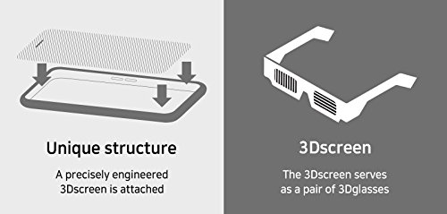
Iphone 6s SNAP 3D is a clear 3D phone case, you can use it to watch 3D movies everywhere with it.
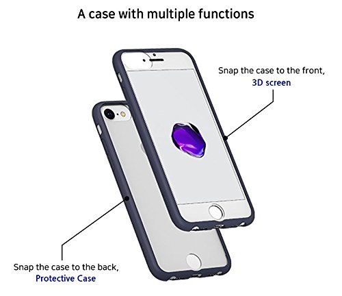
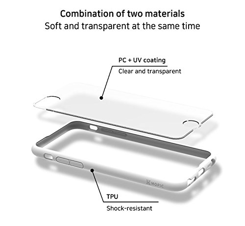
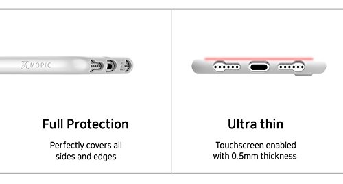
This type is made for Iphone 6s, you can use it as a protective phone case, or 3D viewer. If you want to use it as a 3D viewer, you just take it off and put it on the front of your phone, then it can brings you to a magic world! A magic 3D world! It's light weight, easy to carry as well. When you don't use it to watch 3D contents, you can just put it at the back of smartphones, use it as a protective phone case.
The unique technologies are the lenticular lens on this 3D viewer, better design than the 3D Glasses for smartphones on the current market!


Iphone 6S Snap3D,Snap3D For Iphone 6S,Iphone 6S Snap3D Case,Iphone 6S Snap 3D Viewer
iSID Korea Co., Ltd , https://www.isidsnap3d.com
