
The image memory method is a great way to understand how a transistor works. Think of it like this: energy isn’t created out of nowhere, so the transistor doesn’t generate power—it just converts the energy from the power supply into signal energy. What makes it special is its ability to control large currents with small ones.
Imagine the transistor as a dam with two valves—one big and one small. The small valve can be controlled by hand, while the big one is too heavy to open directly. Instead, the small valve controls the pressure that opens the big one. So when you open the small valve slightly, a trickle of water flows, which in turn opens the big valve, allowing a much larger flow of water to pass through.
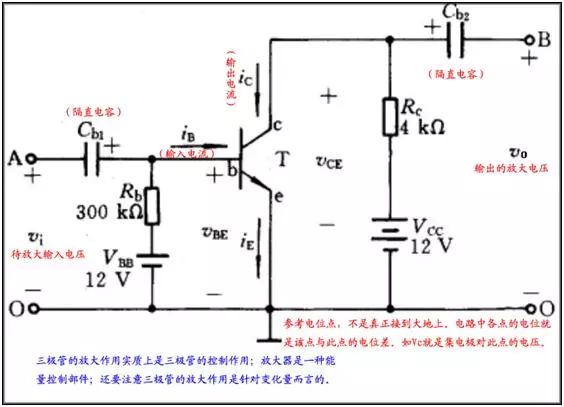
By adjusting the size of the small valve, you can control the amount of water coming from the big valve. This is similar to how a transistor amplifies signals—by controlling the base current (the small valve), you can manage the collector current (the big flow). In terms of current, it’s more accurate to think of the transistor as a current-controlled device.
When the small valve is opened just enough to allow the big valve to move freely, it's like the linear amplification region of the transistor. If the small valve is not opened enough, the big valve remains closed—this is the cutoff region. If the small valve is opened too much, the big valve reaches its maximum flow capacity, which is the saturation region.
If the water level in the reservoir is too high, it might cause the valve to open on its own without any input—similar to reverse breakdown in a diode. There are two types of breakdown: thermal and electrical. Thermal breakdown happens when the power dissipation exceeds the limit, causing overheating and damage. Electrical breakdown, however, is reversible and occurs at lower voltages for Zener breakdown or higher voltages for avalanche breakdown.
In analog circuits, the transistor typically operates in the linear region, where the output is proportional to the input. In digital circuits, it acts more like a switch, either fully on or off. When it’s on, it’s in the saturation region; when off, it’s in the cutoff region. This switching behavior helps reduce power consumption when no signal is present.
In manufacturing, the emitter region of the transistor is heavily doped with electrons, and the base is very thin. When the base-emitter voltage is sufficient (around 0.7V for silicon), electrons from the emitter move into the base and then to the collector, creating a large current. This process illustrates how a small input current can control a much larger output current.
For theoretical understanding, when both the emitter and collector junctions are reverse-biased, the transistor is in cutoff mode. When both are forward-biased, it enters saturation. These states are crucial for determining the transistor’s behavior in different applications.
Moving on to FETs, the JFET is like a smart faucet. The gate controls the flow of current between the source and drain. A negative voltage on the gate narrows the channel, reducing the current. As the voltage increases, the channel becomes narrower, and eventually, the current stops completely.
The MOSFET is similar but has an insulated gate. It uses an electric field to create a conductive channel between the source and drain. By adjusting the gate voltage, you can control the current flow. Unlike JFETs, some MOSFETs can operate in depletion or enhancement modes depending on the applied voltage.
Understanding these components through analogy and theory helps in grasping their real-world applications, from amplifiers to switches, and from simple circuits to complex digital systems.
Hybrid Single Phase Solar Inverter
parallel inverters,hybrid solar inverter 24v,low frequency hybrid solar inverter,hybrid solar inverter 12v,1kw 2kw hybrid solar inverter,10kw hybrid dual mppt solar inverter
Shenzhen Jiesaiyuan Electricity Co., Ltd. , https://www.gootuenergy.com