
IDT's ZMID520x series is an inductive position sensor that uses the principle of line loop and eddy current to generate inductance to detect the position of a conductive object sliding or rotating on the coil. Rotation detection 360 degrees in all directions, PWM digital output, overvoltage, inverting pole Saturation, ESD and short circuit protection, 10-bit resolution, meeting automotive standard AEC-Q 100, grade 0, operating temperature -40 ° C to 150 ° C, mainly used in rotating position sensors up to 360 degrees such as steering angle sensor, replacement Potentiometers, small angle sensors or arc motion sensors such as valve sensors, automotive level sensors and linear motion sensors such as liquid level sensors. This article describes the main features of the ZMID520x series, functional block diagrams, application circuits and evaluation boards ZMID520x EVK main features, main components Distribution diagram, ZMID5201/02/03 demonstration board circuit diagram, bill of materials and PCB design.
The ZMID520x uses the physical principles of inducTIon in a wire loop and eddy currents to detect the posiTIon of an electric conducTIng target that is sliding or rotaTIng above a set of coils, consisting of one transmitter coil and two receiver coils.
The three coils are typically printed as copper traces on a printed circuit board (PCB). They are arranged such that the transmitter coil induces a secondary voltage in the receiver coils that depends on the position of the metallic target above the coils.
A signal representative of the target's position over the coils is obtained by demodulating and processing the secondary voltages from the receiver coils. The target can be any kind of metal, such as aluminum, steel or a PCB with a printed copper layer.
The ZMID5202 is an inductive position sensor IC with PWM output, used for absolute rotary and linear motion sensing in automotive, industrial and consumer applications. The ZMID5202 uses the physical principles of induction in a wire loop and eddy currents to detect the position of a metallic The three coils are typically printed as copper traces on a printed circuit board (PCB). They are arranged such that the transmitter coil induces a Secondary voltage in the receiver coils which depends on the position of the metallic target above the coils. After demodulating and processing the secondary voltages from the receiver coils, a signal representative of the metallic target's position over the coils is obtained.
The ZMID5201/-02-/03 ICs are fully qualified to the automotive standard AEC-Q 100, grade 0 from -40°C up to 150°C ambient temperature.
ZMID5202 main features:
Inductive principle
Rotation sensing up to a full turn of 360o
PWM digital output
Overvoltage, reverse polarity, ESD and short circuit protection
10-bit resolution
Power or ground loss detection
Facilitates redundant design requirements
Programmable linearity correction
Adaptive gain control supporting a wide range of coil designs
Diagnostic features supporting ISO26262
Supporting up to ASIL-B
Overvoltage and reverse polarity protection up to ±18V
Small 14-TSSOP package
The ZMID520x Evaluation Kit is designed for sensor module evaluation,
Laboratory setup, and module calibration development for
The ZMID520x Family of Inductive Position Sensor ICs.
 ZMID5201: analog interface
 ZMID5202: PWM interface
 ZMID5203: SENT interface
ZMID5202 typical application:
 Rotary position sensors up to 360°; eg steering angle sensors, potentiometer replacement
 Small-angle sensors or arc-motion sensors; eg pedal, vehicle level, or valve sensors
 Linear motion sensors; eg linear-actuator position sensors, fluid-level sensors
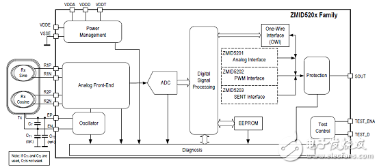
Figure 1. Functional Block Diagram of ZMID5202
The main block diagrams include:
 Power management: power-on-reset (POR) circuit, low drop-out (LDO) regulators for internal supplies
 Oscillator: generation of the transmit coil signal
 Analog front-end: demodulator and gain control for the receive signals
 Analog-to-digital converter (ADC): conversion into digital domain
 Digital signal processing: offset correction, conversion of sine and cosine signals into angle and magnitude, angle range adjustment, linearization, etc.
EEPROM EEPROM: nonvolatile storage of factory and user-programmable settings
 One-wire interface (OWI): programming of the chip through the output pin
 Interface options:
— Analog output for ZMID5201
— PWM output for ZMID5202
— SENT output for ZMID5203
 Protection: overvoltage, reverse polarity , short circuit protection
 Test control: factory testing; connect TEST_D and TEST_ENA pins

Figure 2. ZMID5202 application circuit
Evaluation Board ZMID520x EVK
The main purpose of the ZMID520x Evaluation Kit is communicationbetween the user's computer and the ZMID520x. The computersends commands and data via its USB port to the ZMIDCommunication Board.
The microcontroller on the Communication Board interprets thesecommands and relays them to the ZMID520x located on the ZMID520x Demo Board using the one-wire interface (OWI) communicationinterface.
The microcontroller also forwards data bytes from the ZMID520xback to the computer via the USB connection. These bytes canbe sensor readings, raw analog-to-digital converter (ADC) datafrom analog outputs, or ZMID520x EEPROM contents.
The ZMID520x AID EVK Application Software is a graphical user interface (GUI) is provided online for the kit. It supports allZMID520x configurations and enables the user to intuitivelyunderstand the functionality of the ZMID520x as well asperforming measurements.
The ZMID520x Evaluation Kit is designed for sensor module evaluation, laboratory setup, and module calibration development for the ZMID520x Family of Inductive Position Sensor ICs.
 ZMID5201: analog interface
 ZMID5202: PWM interface
 ZMID5203: SENT interface
The main purpose of the ZMID520x Evaluation Kit is communicationbetween the user's computer and the ZMID520x. The computersends commands and data via its USB port to the ZMIDCommunication Board.
The microcontroller on the Communication Board interprets thesecommands and relays them to the ZMID520x located on the ZMID520x Demo Board using the one-wire interface (OWI) communicationinterface.
The microcontroller also forwards data bytes from the ZMID520xback to the computer via the USB connection. These bytes canbe sensor readings, raw analog-to-digital converter (ADC) datafrom analog outputs, or ZMID520x EEPROM contents.
The ZMID520x AID EVK Application Software is a graphical user interface (GUI) is provided online for the kit. It supports allZMID520x configurations and enables the user to intuitivelyunderstand the functionality of the ZMID520x as well asperforming measurements.
Evaluation board ZMID520x EVK main features:
 USB “plug and play†– no driver installation needed
 Small ZMID Communication Board: 5cm  8cm
 One-wire communication interface (OWI) enables quick and easy configuration and calibration of the ZMID520x using theuser's computer
 PWM, analog or SENT reading of the output depending onproduct
 The design allows easy swapping of ZMID520x Demo Boards
 Ability to connect and evaluate an external module board
— No external power supply needed
— External module is supplied from the ZMID520x DemoBoard
The evaluation board ZMID520x EVK includes:
 ZMID520x Demo Board with printed sensor coil
 ZMID Communication Board
 Micro-USB cable
 Kit software is available for download from the IDT web site:
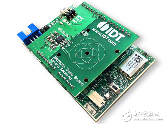
Figure 3. Evaluation board ZMID520x EVK outline drawing
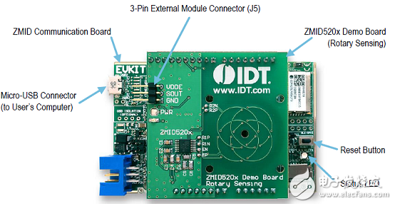
Figure 4. Evaluation board ZMID520x EVK main components distribution map
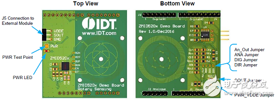
Figure 5. ZMID520x Rotating 360 Degree Demo Board Overview
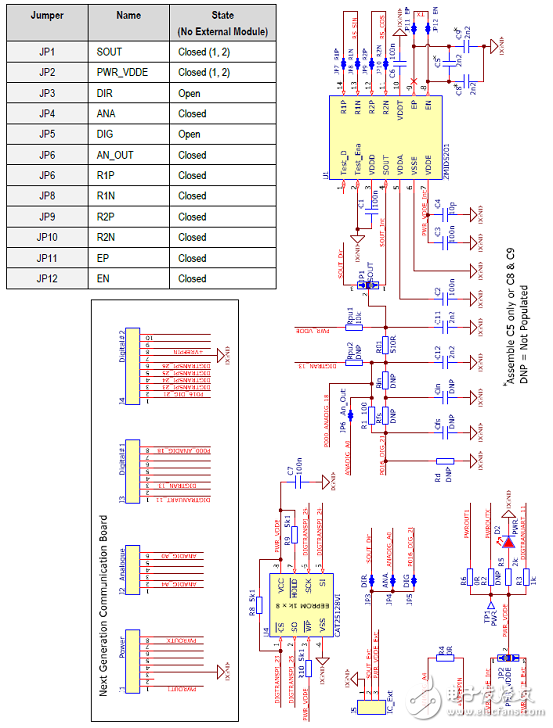
Figure 6. ZMID5201 Demo Board Circuit Diagram
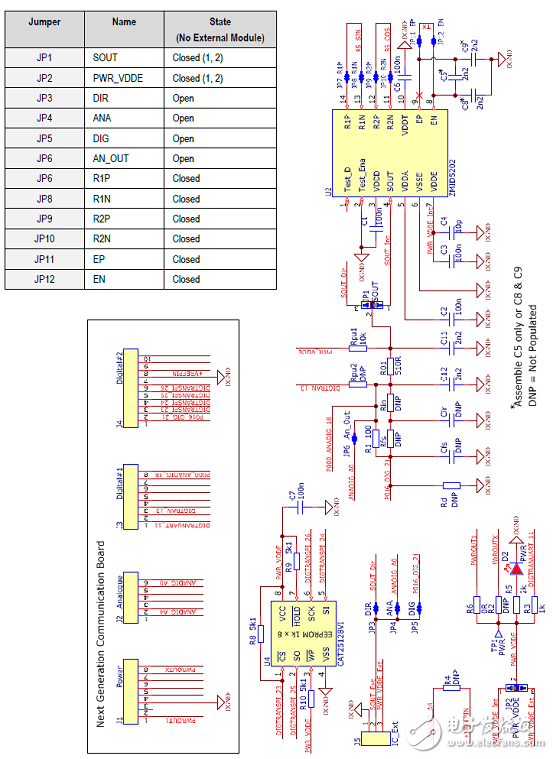
Figure 7. ZMID5202 Demo Board Circuit Diagram
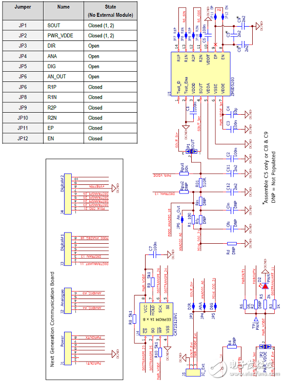
Figure 8. ZMID5203 Demo Board Circuit Diagram
ZMID520x rotating 360 degree demo board material list:
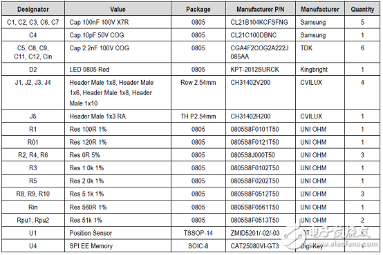
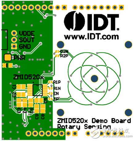
Figure 9. ZMID520x Rotating 360 Degree Demo Board PCB Layout (Top)
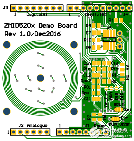
Figure 10. ZMID520x Rotating 360 Degree Demo Board PCB Layout (Bottom)
Cell Phone Case, Mobile Phone Covers, Clear Phone Case, Mobile Phone Case, TPU Phone Case, Silicone Phone Case
Shenzhen Jianjiantong Technology Co., Ltd. , https://www.jjtphonesticker.com