Current sensor details
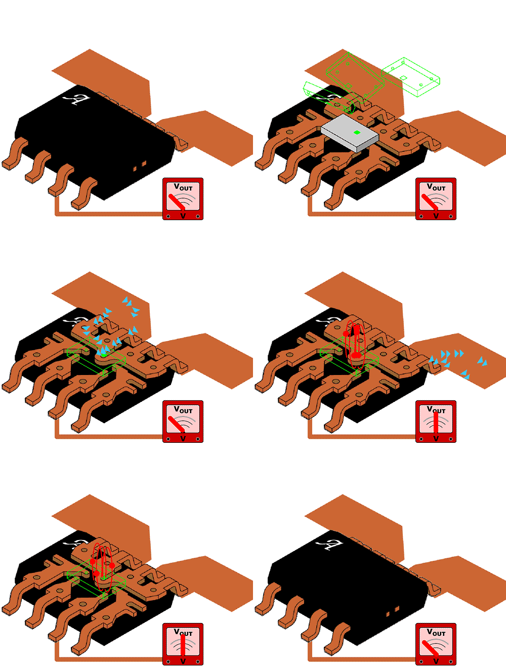
The current sensor is a detecting device that can sense the information of the measured current, and can transform the detected information into a certain signal to meet the requirements of a certain standard or other required form of information output to meet the requirements. Requirements for the transmission, processing, storage, display, recording and control of information.
Current sensors, also called magnetic sensors, can be used in home appliances, smart grids, electric vehicles, wind power, etc., and we use many magnetic sensors in our lives, such as computer hard drives, compasses, household appliances, and so on.
The current sensor is an active module, such as a Hall device, an op amp, and a final power tube, all of which require operating power and power consumption.


(1) The output ground is concentrated on the large electrolysis to facilitate noise reduction.
(2) Capacitor bit uF, diode is 1N4004.
(3) The transformer is based on the power consumption of the sensor.
(4) The operating current of the sensor. Direct inspection (no amplification) power consumption: maximum 5mA; direct detection amplification power consumption: maximum ± 20mA; magnetic compensation power consumption: 20 output current; maximum consumption operating current 20 output current 2 times. The power consumption can be calculated based on the operating current consumed.
Current sensor characteristics
Whether the Hall sensor is open-loop or closed-loop, the basic performance is not much different. The basic advantages are: fast response time, low temperature drift, high precision, small size, high frequency bandwidth, strong anti-interference ability and strong overload capability.
How to choose - current sensor
A. When selecting the current sensor, it is necessary to pay attention to whether the hole size can ensure that the wire can pass through the sensor;
B. When selecting the current sensor, it is necessary to pay attention to whether the application environment of the site has special environment such as high temperature, low temperature, high humidity and strong earthquake;
C. When selecting the current sensor, it is necessary to pay attention to whether the spatial structure is satisfied;
Current sensor usage instructions
A. Pay attention to the exposed conductive part of the terminal when wiring, try to prevent ESD impact, and require engineers with professional construction experience to wire the product. The connecting wires of the power supply, input and output must be correctly connected, and they must not be misaligned or reversed, otherwise the product may be damaged.
B. The installation environment of the product should be free of conductive dust and corrosion.
C, severe vibration or high temperature may also cause damage to the product, must pay attention to the use of the occasion.
Current and voltage sensor usage precautions
(1) The current sensor must be appropriately selected according to the rated effective value of the measured current. If the measured current is excessive for a long time, it will damage the final power amplifier tube (refer to the magnetic compensation type). Under normal circumstances, the overload current of 2 times should not exceed 1 minute.
(2) The voltage sensor must be connected to a current limiting resistor R1 on the primary side according to the product description so that the primary side receives the rated current. Under normal circumstances, the double overvoltage duration must not exceed 1 minute.
(3) The best accuracy of the current-voltage sensor is obtained under the condition of the primary side rating, so when the measured current is higher than the rated value of the current sensor, the corresponding large sensor should be selected; when the measured voltage is higher than the voltage sensor The current limiting resistor should be readjusted at rated value. When the measured current is less than or equal to the rated value of 1/2 or less, in order to obtain the best accuracy, the number of turns can be used.
(4) The sensor with insulation withstand voltage of 3KV can work normally for 1KV and below AC system and 1.5KV and below DC system. 6KV sensor can work normally for 2KV and below AC system and 2.5KV and below DC system. Be careful not to overpressure.
(5) When used on a device that requires good dynamic characteristics, it is best to use a single copper-aluminum busbar and match the hole diameter. The large or small number of turns will affect the dynamic characteristics.
(6) When used in a high-current DC system, if the working power supply is open or faulty for some reason, the core has a large residual magnetism, which is worth noting. Remanence affects accuracy. The method of demagnetization is to add a working power supply, communicate with the original side and gradually reduce its value.
(7) The ability of the sensor to resist external magnetic field is: a distance of 5 to 10 cm from the sensor, which is more than twice the current value of the primary side of the sensor, and the generated magnetic field interference can resist. When three-phase high-current wiring, the phase-to-phase distance should be greater than 5 to 10 cm.
(8) In order to make the sensor work in the best measurement state, the simple typical regulated power supply described in Figure 1-10 should be used.
(9) The magnetic saturation point of the sensor and the saturation point of the circuit make it have a strong overload capability, but the overload capability is time-limited. When the test overload capability is exceeded, the overload current of more than 2 times must not exceed 1 minute.
(10) The temperature of the primary current busbar shall not exceed 85 °C. This is determined by the characteristics of ABS engineering plastics. The user has special requirements and can choose high temperature plastic as the outer casing.
The superiority of current sensor in use
(1) Non-contact detection. In the re-engineering of imported equipment, as well as the technical transformation of old equipment, the superiority of non-contact measurement is shown; the electrical wiring of the original equipment can be measured without changing the current.
(2) The disadvantage of using the shunt is that it can not be electrically isolated, and there is also insertion loss. The larger the current, the larger the loss and the larger the volume. It is also found that the shunt has inevitable electricity when detecting high frequency and large current. Inductive, can not truly transmit the measured current waveform, and can not truly pass the non-sinusoidal waveform. The current sensor completely eliminates all kinds of drawbacks above the shunt, and the accuracy and output voltage value can be the same as that of the shunt, such as accuracy 0.5, 1.0, output voltage 50, 75mV and 100mV.
(3) It is very convenient to use. Take a LT100-C type current sensor, connect a 100mA analog meter or digital multimeter to the M terminal and the power supply zero end, connect the working power supply, and put the sensor on the wire loop. The current value of the main circuit 0~100A can be accurately displayed.
(4) The conventional current-voltage transformer has a high precision in the specified sinusoidal operating frequency although it has a large operating current voltage level, but it can be adapted to a very narrow frequency band and cannot transmit DC. In addition, there is a magnetizing current during operation, so this is an inductive device, so that it can only be tens of milliseconds in response time. It is well known that the secondary side of the current transformer will create a high voltage hazard once it is opened. In the use of multi-channel acquisition of signals in the detection of microcomputers, people are looking for ways to isolate and collect signals. The current-voltage sensor inherits the advantages of reliable insulation of the primary and secondary sides of the transformer, and solves the defect that the transmission transmitter is expensive and requires a transformer. It provides an opportunity for analog-to-digital conversion for automated management systems such as microcomputer testing. In use, the sensor output signal can be directly input to the high-impedance analog meter or digital panel meter, or can be processed twice, the analog signal is sent to the automation device, and the digital signal is sent to the computer interface.
In high-voltage systems above 3KV, current and voltage sensors can be combined with traditional high-voltage transformers to replace traditional power transmitters, providing convenience for analog-to-digital conversion.
(5) The traditional detection components are limited by many factors such as the specified frequency, the specified waveform, and the response lag. They cannot adapt to the development of high-power converter technology, and the new generation of Hall current and voltage sensors, as well as current and voltage sensors and true The combination of active branch AC/DC converters has become an integrated transmitter and has become the best detection module. In addition, the development of electronic power devices to high frequency, modularization, componentization, and intelligence has made device designers comfortable, which will be an epoch-making fundamental change in the history of electronic power technology.
1. Wide measurement range: It can measure the current and voltage of arbitrary waveforms, such as DC, AC, pulse, triangle waveform, etc., and even faithfully reflect transient peak current and voltage signals;
2. Fast response: The fastest response time is only 1us.
3. High measurement accuracy: its measurement accuracy is better than 1%, which is suitable for the measurement of any waveform. The common transformer is an inductive component that affects the waveform of the signal under test after being connected. Its general accuracy is 3%~5%, and it is only suitable for 50Hz sinusoidal waveform.
4. Good linearity: better than 0.2%
5. Good dynamic performance: fast response time, less than 1us; common transformer response time is 10~20ms.
6. Working frequency bandwidth: Signals in the frequency range of 0~100KHz can be measured.
7. High reliability, average trouble-free working time: average unreasonable obstacle time > 5 10 hours
8. Strong overload capability and large measuring range: 0---tens of amps to tens of amps
9. Small size, light weight and easy to install.
China Electric Car Charger,Electric Vehicle Charging Stations,Electric Car Charging Stations,Floor Mounted Ac Ev Charger, we offered that you can trust. Welcome to do business with us.
Electric Car Charger,Electric Vehicle Charging Stations,Electric Car Charging Stations,Floor Mounted Ac Ev Charger
Shenzhen Hongjiali New Energy Co., Ltd. , https://www.hjlcharger.com
