
The electrical system diagram mainly includes electrical schematic diagram, electrical layout diagram, electrical installation wiring diagram, etc. The drawing software includes electrical CAD, protell99, Cadence and so on.
Electrical schematic
The electrical schematic is a type of electrical system diagram. It is drawn according to the working principle of the control line diagram, and has a simple structure and a clear hierarchy. Mainly used to study and analyze the working principle of the circuit.
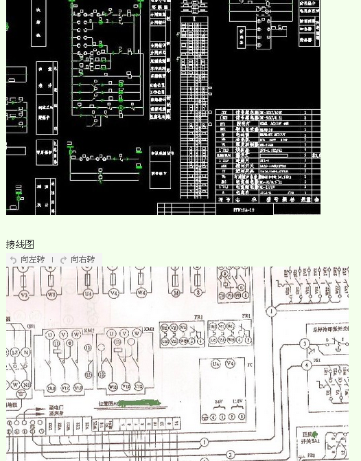
Wiring diagram
Electrical installation wiring diagrams are provided to provide detailed information on the electrical connections between the various installation wiring diagram items, including connection relationships, cable types, and routing lines, for wiring of equipment, equipment, or kits.
Difference between electrical schematic and wiring diagram
Schematic: It is to see his general situation (why so connected)
Wiring diagram: It is to use every component and component connection involved in electrical assembly and maintenance.
The schematic diagram is the working principle diagram of the circuit. The meaning of the expression is how the various components work. The wiring diagram is the expression of how the components and components are connected. The installation diagram is the expression of the dimensions of the components in the specific position of the control cabinet.
Some schematics can be used as wiring diagrams (that is, the function of wiring diagrams is added to the schematic).
The schematic diagram refers to the detailed circuit diagram, the focus is on the electrical principle, knowing why this is the wiring.
The wiring diagram is used for wiring the operator. The key point is to distinguish the complicated line type line numbers and facilitate wiring. It can be wired according to the schematic diagram, but it is easy to make mistakes when there are many online, and it is very demanding for workers. The line number and model of the marked line are not shown, the wiring principle is not displayed, the construction is convenient, and the requirements for the workers are low.
Schematic and wiring diagram
Common terms
Loss of voltage and undervoltage protection: It is realized by the electromagnetic mechanism of the contactor itself. When the power supply voltage is seriously too low or loses pressure, the armature of the contactor releases itself, and the motor loses power and stops.
Jog and long movement: There is no normally open contact of the contactor at both ends of the jog button; the two ends of the long move button are connected to the normally open contact of the contactor.
Interlock control: When one branch of the control line is energized, the other branch is guaranteed to be powered off.
Double interlock: Dual interlock can be switched from "one-back-stop" directly from one operating state to another. Direct start: The power supply voltage is directly applied to the terminal of the motor. This control circuit has a simple structure and low cost. It is only suitable for the infrequent start of the motor and cannot realize automatic control over long distances.
Undervoltage start-up: Refers to the starting device to properly reduce the voltage and then add it to the stator winding of the motor to start. After the motor starts running, the voltage is restored to the rated value for normal operation.
Single Burner Electric Hotplate
Portable Hot Plate,Single Burner Electric Hotplate,Hot Plates,Hot Plates With Stainless Housing
Shaoxing Haoda Electrical Appliance Co.,Ltd , https://www.hotplates.nl