
One of the features of the USB standard is to power the inserted USB peripheral from the host . From the past serial and parallel port changes to USB , this advancement can greatly increase the number of various devices connected to the PC .
In addition to direct external device powered USB, USB is more a function of battery charging is carried out using a USB supply. Since many portable devices ( such as MP3 players, PDAs) exchange information with PCs , battery charging and data exchange simultaneously on one cable will greatly enhance the convenience of the device. The battery-powered and USB features combine to expand the "unrestricted" means (such as a PC or mobile web camera is connected is not connected to the work PC) operating range. In many cases, it is not necessary to carry an inconvenient AC adapter.
Charging the battery from USB can be complicated or simple, depending on the USB device requirements. The factors that affect the design are usually "cost", "size" and "weight". Other important considerations include: 1) When the device is plugged into the USB port, how fast can the device with a discharged battery enter a full working state; 2) the allowed battery charging time; 3) the power budget limited by USB ; 4) Including the necessity of AC adapter charging. After detailing USB from the power point of view , we will give solutions to these problems.
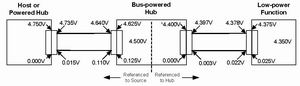
Figure 1 USB voltage drop ( from Universal Serial Bus specification Rev2.0)
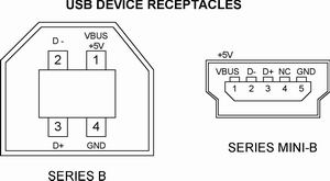
Figure 2 USB device jack
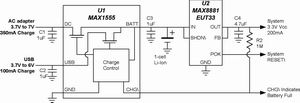
Figure 3 does not require enumeration for simple charging 100mA from USB and 350mA from AC adapter , because the USB charging current does not exceed "one unit load" (100mA) . The 3.3V system load always draws current from the battery.
USB power
All host USB devices ( such as PCs and laptops ) can supply at least 500mA or provide 5 "unit loads" per USB socket . In the USB predicate, "one unit load" is 100mA . The self-powered USB jack can also provide 5 unit loads. The bus-powered USB jack is guaranteed to provide a unit load (100mA) . According to the USB specification and the description in Figure 1 , the minimum effective voltage from the USB host or power supply jack is 4.5V at the peripheral end of the cable , while the minimum voltage from the USB bus power supply jack is 4.35V . When these voltages are used to charge a lithium ion battery ( typically 4.2V is required ) , the remaining amount is very small.
The current drawn by all devices plugged into the USB port must not be greater than 100mA . After communicating with the host, the device can decide whether it can occupy the entire 500mA .
The USB peripheral contains one of the two jacks. Both jacks are smaller than those in PCs and other USB hosts. The " SeriesB" and smaller " Series Mini-B " jacks are shown in Figure 2 . Get power from Series B pins 1 (+ 5V) and 4 ( ground ) and Series Mini-B pins 1 (+ 5V) and 5 ( ground ) .
Once connected, all USB devices need to be recognized by the host. This is called "enumeration". During the identification process, the host determines the power supply of the USB device and whether to supply power to it. For approved devices, the load current can be increased from 100mA to 500mA .
Simple USB / AC adapter charging circuit
Some very basic devices do not want additional software overhead, which is required for the classification and optimal use of effective USB power supplies. If the load current of the device is limited to 100mA ( called "one-unit load" in USB ) , then any USB host or self-powered jack can power the device. For such a design, a very basic charger and regulator circuit is shown in Figure 3 .
Whenever the device is connected to USB or plugged into an AC adapter, this circuit charges the battery. At the same time, the system load is always connected to the battery. In such a case, a simple linear regulator (U2) can supply up to 200mA . If the system continuously draws such an amount of current and the battery is charging from the USB at 100mA , the battery will still be discharged because the load current exceeds the charging current. In most small systems, the peak load only occurs for a fraction of the total working time, so only the average load current needs to be less than the charging current, and the battery will still charge. When the AC adapter is connected , the maximum current of the charger (U1) increases to 350mA . If the USB and AC adapters are connected at the same time , the AC adapter automatically assumes the priority power supply status.
A characteristic of U1 is required by the USB specification (which is also the rule of a general charger ) , that is, it never allows current to be fed back from the battery or other power input to the power input. In general chargers, the input diode can be guaranteed, but the difference between the minimum USB voltage (4.35V) and the required lithium-ion battery voltage (4.2V) is very small, even using Schottky Diodes are also inappropriate. For this reason, all reverse current paths are disconnected in the U1 IC .
The circuit in Figure 3 has some limitations, making it unsuitable for some rechargeable USB devices. The most obvious limitation is its relatively low charging current, which makes charging lithium-ion batteries greater than a few hundred milliamps an hour time-consuming. The second limitation is that the load ( linear regulator input ) is always connected to the battery. In this case, the system cannot work immediately after insertion, because the battery is deeply discharged, and there is a delay before the battery reaches a sufficient voltage to make the system work.
Load switching and enhanced circuits
In more advanced systems, the charger or around the charger needs some enhanced performance. This includes selectable charging current to suit the power supply capability of different power sources or batteries, load switching when plugged into a power source, and overvoltage protection. The circuit shown in Figure 4 adds these functions. It is implemented by means of an external MOSFET driven by a charger IC voltage detector .
MOSFETs Q1 and Q2 and diodes D1 and D2 bypass the battery and directly connect the active (USB or AC adapter ) power input and load. When the power input is valid, the DC input has priority; U1 prevents both inputs from being active at the same time. Diodes D1 and D2 prevent reverse current between inputs generated through the "system load" power path, and the charger has a built-in circuit to exclude reverse current through the charging path ( at BATT) .
MOSFET also provides AC adapter overvoltage protection ( up to 18V) . The under / over voltage monitor keeps the AC adapter voltage between 4V and 6.25V .
MOSEFT Q3 turns on when there is no valid external power supply, connecting the battery to the load. When the USB or DC power supply is connected, the PON ( power switch ) output immediately disconnects Q3 , disconnecting the battery from the load. The system can work immediately when the external power supply is added, even if the battery is deeply discharged or damaged.
When the USB is connected , the USB device communicates with the host to determine whether the load current can be increased. If the host allows, the load starts at one unit load and increases to 5 unit loads. The current range of 5 to 1 unit load presents a problem for general chargers ( not designed for USB) . Although the accuracy of general chargers can meet the requirements of high current, it usually cannot meet the requirements in low current settings, which is caused by the deviation of the current detection circuit. The result is that the small-scale charging current (1 unit load ) must be set low enough to ensure that the 100mA limit is not exceeded . For example, for a 10% accuracy of 500mA , the output must be set to 450mA to ensure that it does not exceed 500mA . This is only acceptable; however, in order to ensure that the low charging current does not exceed 100mA, its rated current must be set to 50mA , and the minimum value may be 0mA, which is obviously unacceptable. If USB charging is effective in both ranges, sufficient accuracy is required so that the maximum possible charging current does not exceed the USB limit.
In some designs, the system power supply requires a USB budget of less than 500mA to power the load and the rechargeable battery separately, but using an AC adapter is not a problem. The circuit shown in Figure 5 ( simplified subsystem of Figure 4 ) is an economical connection method. The USB power supply is not directly connected to the load. Charging and system operation still occur on the USB power supply, but the system remains connected to the battery, and its limitations are the same as in Figure 3 : When the USB is connected , if the battery is deeply discharged, the system can have a delay before working. When DC power is connected, the operating state of FIG. 5 is the same as FIG. 4, no waiting time, regardless of the state of the battery, because Q2 is turned off, the DC input to the load from the battery system through D1.
NiMH battery charging circuit
Although lithium ion batteries provide the best performance for most portable devices, NiMH ( nickel metal hydride ) batteries are still a viable option for low-cost designs. When the load requirements are not too strict, a good way to keep costs low is to use NiMH batteries. This requires a DC-DC converter to boost, generally from 1.3V battery voltage to the voltage available for the device ( generally 3.3V) . Since any battery-powered device requires a voltage regulator, the DC-DC converter is just a different voltage regulator.
The circuit shown in Figure 6 uses a unique method to charge the NiMH battery and does not use an external FET to switch the system load between the USB input and the battery. The "charger" is actually a DC-DC boost converter (U1) operating under current limitation . A current between 300 and 400 mA to charge the battery. Although there is no precise current source, it has proper current control and can maintain current control even when the battery is short-circuited. The biggest advantage of the DC-DC charging topology over the general linear scheme is that it can effectively use the limited USB power resources. When charging at 400mA, NiMH batteries from the USB input circuit draws only 150mA. The remaining 350mA is used for the system when charging .
Diode D1 pulls the load from the battery to the USB . When USB is not connected , the boost converter produces a 3.3V output. When connected to USB , D1 pulls up the DC-DC boost converter (U2) output to about 4.7V . When the U2 output is pulled up, it automatically turns off and the current drawn from the battery is less than 1mA . When the USB connection is not acceptable for changing the output from 3.3V to 4.7V , a linear regulator in series with D1 can be added .
The limitation of this circuit depends on the system to control the end of charging. U1 is only used as a current source, if you don't care about it for a long time, it will overcharge the battery. R1 and R2 set the maximum output voltage of U1 to 2V as a safety limit. "Charge Enable" ( "Charge Enable") functions as an input end of the charging system and the effect of reducing the effect of the load current prior to enumeration 16-Port HUB USB2.0
USB 2.0 standard offers data transfer speeds of up to 480 Mbps, making it suitable for most common peripherals and devices.This hub is backward compatible with USB 1.1 devices, ensuring that you can connect older devices without any issues.
It often comes with a separate power adapter to provide sufficient power to all the connected devices, ensuring stable and reliable performance.
16-Port USB 2.0 Hubs may include additional features like LED indicators for each port, allowing you to easily identify which ports are in use.This can be particularly useful when dealing with a large number of connected devices.
Hubs offer overcurrent protection, which safeguards your devices from potential damage caused by power surges or short circuits.This feature ensures the safety of your valuable equipment.
16-Port USB 2.0 Hub is an excellent solution for individuals or businesses that require multiple USB connections.It provides convenience, flexibility, and efficiency by expanding the connectivity options of your computer or laptop, allowing you to connect and use multiple devices simultaneously. Whether you are a professional or a tech enthusiast, this hub can greatly enhance your productivity and simplify your daily tasks.
Multi-port intelligent A-port hub,16-Ports HUB2.0,16-port A-port cabinet type hub,Smart USB2.0 hub
shenzhen ns-idae technology co.,ltd , https://www.best-charger.com