
In order to avoid traffic accidents caused by rear-end collision between the two vehicles in the same lane, the project developed a vehicle distance safety distance intelligent control and self-brake simulation system based on the cause of the rear-end collision. The simulation system uses the Hall sensor and the acceleration sensor to measure the rear vehicle speed Vb, and uses the ultrasonic echo ranging principle to measure the vehicle spacing â–³S of the front and rear vehicles. The data is processed by the stm32f103zet6 single-chip microcomputer, and the rear vehicle is automatically adjusted according to the operating conditions of the two vehicles. Driving speed, thus achieving intelligent control of the safe distance between the rear and front vehicles. The actual test shows that the system can realize the intelligent control of the safety distance and meet the design requirements.
This article refers to the address: http://
In recent years, in the national road traffic accidents, rear-end accidents accounted for about 1/10 of all traffic accidents. With the development of social economy, private cars have increased, and road traffic congestion has been very serious in recent years. The inability to control vehicle speed in a timely manner and the delay in human response time are the main causes of these problems. To solve these problems, manual driving can be changed to automatic driving, and accurate driving must be accurately measured to achieve automatic driving. The project first improved the speed measurement method, used the acceleration sensor to compensate the error of the traditional Hall sensor speed measurement, realized the accurate measurement of the speed, and then accurately measured the front and rear distance, and realized the intelligent control of the safe distance through the automatic control algorithm.
1 system overall design
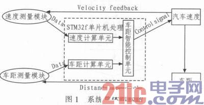
The structure diagram of the simulation system is shown in Figure 1. The real-time data is obtained by the speed measurement module and the distance measurement module, and the obtained data is sent to the stm32f single-chip microcomputer (the stm32f single-chip microcomputer is a 32-bit microprocessor based on the ARM-CM3 core, The data processing unit with a system frequency of 72 MHz, low power consumption and powerful function is operated and processed, and the processing result is sent to the intelligent control unit of the vehicle distance, thereby realizing the control of the vehicle speed and the intelligent control of the vehicle safety distance.
2 program, principle and technical description
2.1 After car speed Vb measurement
1) Wheel speed → driving speed The constant magnet is mounted on the wheel axle of the wheel at a certain angular interval. By using the Hall effect, the signal adjustment circuit of the small voltage output is designed and configured to obtain the rotation of the axle in a certain period of time (Δt). Angle spacing (△ Ω), according to the wheel radius parameter, get the rear car speed
2) Linear acceleration → next moment speed is equal to the integral of acceleration versus time. An acceleration sensor made by the principle of piezoelectric effect acquires the linear acceleration a of the trolley and calculates the velocity vn at the next moment.
2.2 Two-vehicle relative displacement â–³ S measurement
Taking the rear car of the movement as the reference object, the displacement of the moving front and rear vehicles is the relative displacement of the two vehicles ΔS. The ultrasonic wave is emitted by the ultrasonic transmitting device, and the echo distance measuring principle is used, according to the ultrasonic wave (wave velocity) received by the receiver. The time difference ΔT, timely acquisition of the relative displacement of the two vehicles △ S
The relative speed vr of the two vehicles is measured. The relative speed of the preceding vehicle is measured with the moving rear vehicle as the reference object. The experimental principle is: the ultrasonic wave is transmitted twice in succession at time T, and the relative distance is obtained twice. speed. According to the relative speed of the vehicle, the motion information of the preceding vehicle is obtained, thereby providing a basis for the adjustment of the rear vehicle speed.
2.3 Safety Distance Intelligent Control Experimental Principle
Set the safety distance of the automatic control algorithm based on vehicle performance. According to vb, â–³s, vr, closed-loop control is adopted, and the rear car speed is automatically adjusted in real time, so that the rear car and the front car maintain a safe distance, and the safe distance control and self-brake are realized. The principle is shown in FIG. 2 .
3 test data, technical parameters and technical analysis
It is the key to realize the intelligent control of the distance of the system by ensuring the accuracy of the ultrasonic ranging system and the speed measurement of the Hall device. In the experiment, we measured and analyzed the relevant parameters, recorded and analyzed as follows.
3.1 Experimental data and analysis of ultrasonic ranging module
1) Experimental data of ultrasonic ranging module Experimental method: Firstly, the distance between the ultrasonic distance measuring module and the obstacle in front is accurately determined, and the distance is the actual distance. Then start the ultrasonic module and get the test data.
2) Experimental data analysis and conclusion According to the test data and data comparison analysis, the two data curves agree well (as shown in Figure 3). When the distance between the ultrasonic module and the front obstacle is less than 200 cm, the maximum value of the relative error of the test is 3.28%, and increases with the increase of the distance. When the distance between the ultrasonic module and the front obstacle is greater than 200 cm, the relative error increases significantly.
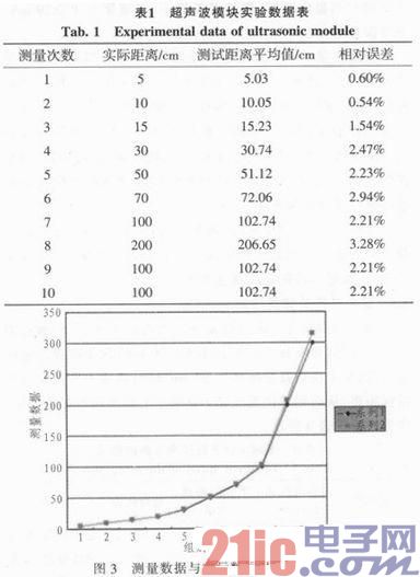
The main cause of the error is that the angle between the mounting position of the module and the obstacle changes with the distance, and the error can be corrected in the algorithm according to the cause.
In this work system, the ultrasonic module is installed in front of the front of the rear car, and the distance between the rear car head and the front car tail (ie, the safety distance between the two cars) is set within 200 cm. From the above data analysis, the distance range test is known. Both the error and the absolute error are small. It can be seen that the ultrasonic ranging module satisfies the design requirements of the system.
3.2 Experimental data and analysis of speed measurement
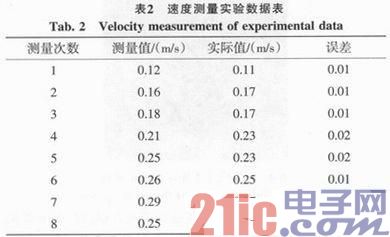
1) Experimental data of velocity measurement Experimental method: This system uses Hall sensor for velocity measurement, and uses acceleration sensor to measure the velocity to improve the accuracy of system velocity measurement. In the experiment, we compare the display data with the measured data to obtain The following data.
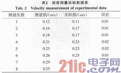
2) Analysis and conclusion of experimental data According to the above data analysis, when the speed of the trolley is 0.12~0.29 m/s, the stability of the speed measurement is good, and the measurement error is small; when the speed is greater than 0.29 m/s, the measurement error increases.
The main reason for the error in speed measurement is that the model car used in this set of simulation system has a small wheel (5.5 cm in diameter), which makes the number of magnetic beads installed on the wheel in the Hall sensor speed measuring module too small (3) The number of signal pulses that can be obtained by rotating the wheel for one revolution is only three, which makes the measurement error larger. There are two error correction methods: method one, using acceleration sensor to reduce the error; method two, using the same principle of photoelectric code wheel speed detector instead of Hall sensor for pulse signal acquisition.
In this work, the running speed of the trolley is 0.12~0.29 m/s. In addition, the acceleration sensor is added to correct the measurement output of the Hall sensor, so that the error is small and meets the speed measurement requirements of the simulation system.
3.3 Intelligent control of safe distance
In order to check whether the safety distance maintenance system meets the requirements, we fixed the road sign (stop sign position), let the car pass the set reference line at different speeds, the reference line and the road sign distance is 50 cm, and then measure the car parking time. The distance from the road sign to determine whether the system is up to standard. The experimental site is shown in Figure 4. The experimental data is shown in Table 3.
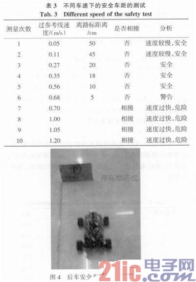
From the above data analysis, the simulation system can realize the intelligent control of the safe distance and the function of the self-brake system when the speed is lower than 0.7 m/s. When the car is overspeed, the maximum safe distance can be adjusted according to the speed of the car to ensure safe driving.
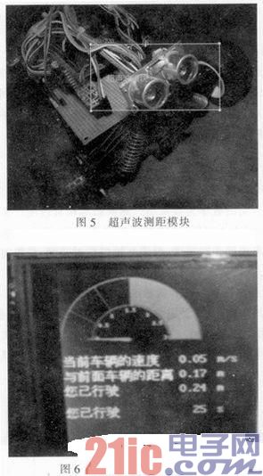
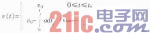
The ranging module of the system and the wireless system operating parameter display module are shown in FIG. 5 and FIG. 6. The user-friendly wireless handheld parameter display provides clear, real-time display of system speed, mileage, and distance to the vehicle.
4 The scientific and advanced nature of the work
1) Velocity measurement At present, most domestic methods for measuring vehicle speed use Hall sensors for speed measurement. However, in real life, especially on highways, it is often found that the display speed of the car code dial is greater than the actual speed. This error is not caused by the accuracy of the sensor, but by the fact that the wheel is slippery due to poor grip. The speed measurement of the Hall sensor is converted into the speed of the car by measuring the wheel speed of the car. In order to improve this problem, we take measures to measure the acceleration speed of the car line to compensate for the error caused by this measurement method.
2) Safety distance control After setting the safety distance according to the vehicle performance, during the driving, the front vehicle speed is changed, the rear vehicle can complete the automatic follow-up and adjust the speed, and no rear-end collision occurs with the preceding vehicle. The simulation system can also implement the distance keeping function and the distance warning.
3) Automatic braking system The actual vehicle braking process is a superposition of uniform motion and uniform deceleration motion. As shown in Figure 7, the vehicle speed v(t) is a simple piecewise function:
Where v0 is the vehicle speed before the braking measures are taken and a is the average braking deceleration.
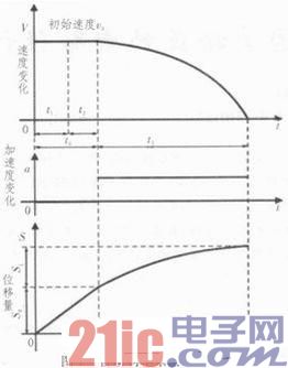
For the speed v (t) integral, the braking distance can be obtained:
When it is detected that there is a static obstacle in front, the car can activate the automatic braking function, emergency braking to prevent collision, and the intelligent driving mode reduces the driver's fatigue.
5 Conclusion
Vehicle safety distance intelligent control and self-brake simulation system through the speed of the accurate test and automatic control algorithm, to achieve the function of automatic maintenance and automatic braking of the front and rear car safety distance in the same lane driving. In practical applications, the occurrence of rear-end collisions can be prevented in real time, the safety of vehicles can be improved, and the driver's psychological burden can be reduced. At the same time, the project results can also be applied to car unmanned driving, providing ideas for automatic driverless driving of automobiles. And technical support, and the system can also be improved to the automatic following system, to solve the delay of manual operation, so as to achieve real-time, sensitive and improved traffic control.
Thunderbolt Cable
Shenzhen GuanChen Electronics Co., Ltd. , https://www.gcneotech.com