
Miniature ultra-remote wireless remote control / data transmission component and its application (Part 2)
3. Special remote control module for remote PTZ camera CSJ-TY300B / RYT02B
1. TY300B transmitter module The PTZ special remote control transmitter module TY300B is based on the T300B to increase the number of buttons and improve the heat dissipation conditions of the high-frequency power amplifier tube, so as to facilitate the continuous launch and expansion for a longer time. The module can be connected with up to eighteen buttons, which can rotate up, down, left and right of the four gimbals and the camera, the focal length, the aperture, the size of the aperture, the start and stop of the outdoor gimbal wiper, and the opening and closing of the camera. Remote wireless operation.
The external dimensions of TY300B and the wiring method of control buttons are shown in Figure 9 and Figure 10:
2. RYT02B receiver module RYT02B gimbal dedicated remote control transmitter module is composed of sound meter frequency stabilization superheterodyne receiver and decoder array, relay drive array and stabilized power supply, and is connected with 8 electromagnetic relays to drive the gimbal and electric The motor on the control camera can realize the fully compatible remote control of AC and DC motors and high and low voltage motors. The switching of the camera power supply and the PTZ motor power supply is also completed by the relay. The appearance of RYT02B is shown in Figure 11; the application wiring diagram is shown in Figure 12.
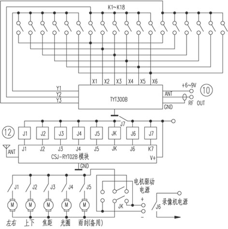
3. Application Refer to Figure 10 to connect the button to the TY300B, the antenna (50Ω impedance) and 6-9V DC power supply, the transmitter can be used, the module comes with power control and emission indication LED, press any button, the LED lights, indicating transmission The machine is transmitting instructions, and the transmitter will stop working when the key is released. Note that the duration of each press of the key must not exceed 30s to avoid overheating of the power amplifier tube. If it is powered by a 6V power supply, the remote control distance is enough? (Generally, it can be satisfied), 9V power supply is not needed, so that the transmitter can work continuously for a long time.
The connection method of the receiving module and the relay, and the contacts of the relay to the PTZ motor and camera motor are shown in Figure 12, where JK is a double-pole double-throw (2 & TImes; 2 conversion) relay, and two sets of normally closed and normally open contacts are used For the rest of the relays, a single contact can be used. The working voltage of the coil is 12V. The contact capacity is selected according to the type and power of the motor on the gimbal and camera.
The gimbal rotates left, right and up and down, the aperture size, the focal length far, near and wiper (standby) operations are all jog structure, that is, the motor moves during the key press, release the key, the motor stops. And PTZ Nos. 1 to 4 are selected for interlock operation, and only one PTZ is controlled at any time. Camera switches 1 to 4 are all bistable, that is, press once to work, press again to stop, then press again to work ...
One transmitter can remotely control four PTZ cameras and cameras. If there are multiple sets of similar devices in the same area, the mutual interference can be avoided by changing the address code. Pin {1} of PT2262 on TY300B has been used to index the number of expansion keys. Pins {7} and {8} are also used as data terminals. Only pins {2} ~ {6} can also be used for address coding, five The tri-state address can accommodate 243 groups of similar equipment working in the same area. Note when coding: the pin connected to the {9} pin of PT2262 (including PT2272) is ground, and the pin connected to {18} is V +. The same and the same code as the matching transmitter. If a transmitter is equipped with four receivers, the address codes of the four receivers and the transmitter must be exactly the same. Please refer to the relevant instruction manual for details on how to use the receiving block.
4. Precautions for the use of remote transmitter / receiver components 1. Transmitter module Power supply selection: The matched power supply must have a low internal resistance and can output a rated current of about 1A. According to the results of the test and comparison, the city power is best supplied by DC stabilized voltage, followed by various rechargeable battery packs with a capacity of more than 300mA. For portable but not commonly used equipment, 9V stacked alkaline batteries (9V580mA, short circuit current up to 6A) can also achieve good results. If the internal resistance of the power supply is high, the transmission distance will become shorter.
Transmitting antenna: The antenna is the high-frequency load of the transmitter and the outlet of high-frequency energy. These components are matched according to the rated load of 50Ω when leaving the factory, so the required antenna is 50Ω, and the length of the wire from the root of the antenna to the soldering point of the antenna on the module is minimized. If it cannot be reduced, it can be connected with a radio frequency coaxial cable with a characteristic impedance of 50Ω.
Transmitting time: The above-mentioned transmitting modules are designed according to the characteristics of wireless remote control that works intermittently. It is recommended that the time of each continuous transmission should not exceed 3s, and the ratio of transmission / stop time is less than 1. For the PTZ remote control module, the continuous transmission time should not exceed 20s. When the distance between the receiving and transmitting components is not too far, the operating voltage can be appropriately reduced, and the transmitter can transmit continuously for a long time.
2. The receiver module R02A / R02B can work even when it deviates from the optimal operating voltage, but it will cause a decrease in the receiving sensitivity. Superheterodyne receivers also have higher matching requirements for antenna impedance, and deviations from 50Ω will cause a sharp decrease in sensitivity.
The superheterodyne receiver assembled with RX3310A as the core also has the disadvantage that it cannot decode due to strong signals and jamming at close range, so it is normal to decode within 3 meters from the transmitter. In contrast, super regenerative receivers do not have this problem.
3. Regarding the remote control distance, the remote control distance is the maximum decodable distance measured on a straight and open ground when the transmitter / receiver module works alone and is equipped with a quarter-wave whip antenna and works vertically under rated conditions. Generally speaking, the distance between the above components (except infrared detection) on the straight line of the city is 2 to 3 kilometers, and the open suburbs can reach 3 to 5 kilometers, or even 7 kilometers.
The data rate also has a greater impact on the communication distance. Generally speaking, the higher the rate, the closer the distance. It is recommended that the data rate be 1.2 to 2.4 kbit / s. On the other hand, computer systems (including microcontrollers) have certain electromagnetic interference to the RF components. If not handled properly, it will cause the wireless transmission distance to become shorter and may not even work properly. The anti-interference measures given in Figure 4b of the previous issue are for reference only. To solve the electromagnetic interference problem satisfactorily, we must start from many aspects such as single-chip computer selection, software design, PCB board wiring and structural design.
Closed Tricycle Electric Vehicle
Three-Wheel Electric,Enclosed Electric Vehicle,Three-Wheeled Electric Vehicle,Closed Tricycle Electric Vehicle
Jinan Huajiang environmental protection and energy saving Technology Co., Ltd , https://www.hjnewenergy.com