
1 Introduction
At present, LED lighting has become more and more extensive. With the development and maturity of power carrier technology, especially the speed and cost of power carrier chips, power carrier technology has been widely used in smart communities, intelligent buildings, automatic meter reading and information appliances. The LED controller combined with power carrier technology and computer technology greatly saves wiring costs and realizes energy-saving and intelligent centralized two-way control.
2 system control scheme
The block diagram of the LED intelligent dimming system is shown in Figure 1.
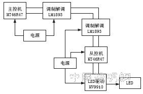
Figure 1 LED intelligent dimming system block diagram
The main control unit is composed of HT46R47, and its function is to use the power carrier modulation and demodulation chip LM1893 to communicate with the slave through the power line.
The slave controller HT46R47 uses the modem chip LM1893 to obtain the command of the master computer through the power line, controls the LED drive current, and sends the working state of the LED to the master through the power line.
3 hardware components
3.1 Modulation and demodulation
The LM1893 is a FSK-based modem chip that can be used for power line carrier communication to achieve reliable serial data half-duplex power line communication with all the functions of transmitting and receiving data. The internal circuit of LM1893 can be divided into two parts: transmission and reception. The working state of the circuit is controlled by the 5-pin transceiver control terminal. When transmitting, the data input from the 17-pin is generated by the FSK modulator to control a set of control currents. The frequency of the internal IOC (current-controlled oscillator) is controlled. The modulated triangular wave of the IOC output is filtered, power amplified from the 10th pin, and then externally The LC frequency selective network and high voltage capacitors enter the power line. When receiving, the signal on the power line is filtered by the coupling capacitor and high frequency, and then selected by the LC parallel resonant circuit. The signal enters the chip through the l0 pin, and the data signal is demodulated through the limiting filter and the PLL (phase locked loop). The signal is processed by the signal of the low-pass filter, the DC cancel circuit and the noise filter circuit, and the signal is output through the 12-pin. In addition, pins 1 and 2 of the integrated circuit are external capacitor terminals of the current control oscillator, and pin 18 is an external resistor terminal for adjusting the carrier frequency. The 8th and 9th feet can be selected from the emitter and base of the external riser to increase the transmit power or short-circuit directly. The 16 pin is used to connect the filter capacitor of the limiting amplifier. Pins 3 and 4 are used to connect the external capacitor and resistor of the phase-locked loop. The choice of parameters determines the locking frequency and capture range of the phase-locked loop.
LM1893 can realize half-duplex communication of serial data. Its main functions are as follows: FSK anti-noise modulation technology, pulse generator with noise filtering can be selected; data transmission rate can reach 4.8kb; sine wave carrier frequency can reduce RF Interference, RF power can be enhanced by 10 times; carrier frequency can be selected between (50 ~ 300) kHz. The signal carrier frequency set in this system is 125 kHz.
3.2 How the LED driver works
The HV9910 is selected for the LED driver. HV9910 Control LED Brightness PWM dimming method: PWM dimming scheme requires IC's PWM-D pin to introduce a PWM signal from the outside. The external PWM signal can come from 1 MCU or 1 pulse generator and meet the requirements of regulating output current. Duty cycle. The success or failure of this PWM dimming mode depends on the external signal, in which the LED current is in two states: the off state and the current value state nominally set by the RSENSE resistor. Between these two states, the average brightness of the LEDs cannot exceed the brightness of the set limit state (ie, the duty cycle is 100%). Therefore, the brightness of the LED can be adjusted from 0% to 100%. The precise PWM dimming method is limited to a small pulse width, and the pulse is derived from a fraction of a low frequency PWM signal.
The recommended design is reasonable between (200 and 500) Hz. If the external control PWM mains direct drive design should pay attention to signal isolation, optocoupler and transformer can be, the module does not provide isolated power supply.
The HV9910 can control all basic type converters, isolated or non-isolated, operating in continuous or discontinuous conduction modes. When the GATE pin of the HV9910 provides a power MOSFET signal, the driver stores energy in one inductor or stores energy in the primary coil of the transformer. Depending on the type of converter, energy may also be transferred directly to the LED. The energy stored in the magnetic element is sent out to the output when the power MOSFET is turned off (FLYBACK mode of operation).
When the voltage at VDD exceeds the UVLO threshold voltage, the GATE pin outputs, the output current is controlled by the peak current of the external power MOSFET, and the source of the MOSFET is connected to a resistor RSENSE that regulates the current, and the voltage across the regulated current resistor is Feedback to the CS pin of the 9910. Once the current ramps up, the voltage on the CS pin exceeds the threshold, the GATE pin output signal is aborted, and the MOSFET is turned off. The threshold for this automatic shutdown has been set to 250mV inside the 9910 and can also be adjusted by changing the voltage at the LD pin. If a soft start is required, the LD pin needs to be connected to a capacitor to raise its voltage, ensuring that the output current through the LED is gradually increased at startup.
3.3 Power Factor Correction
When the output power of the load LED does not exceed 25W, a passive PFC loop can be added to the circuit of Figure 1, which passes the harmonic content requirements of the AC line for Class C appliances in EN61000-3-2. In this typical application, the requirements can be met without an active PFC loop, notable. The PFC loop contains three diodes and two electrolytic capacitors that correct the input AC voltage and improve the harmonic distortion in this circuit, thereby increasing the power factor by more than 0.85.
The main control MCU and the slave MCU are connected to the LM1893 as shown in Figure 1. The MCU TXD and LM1893 data input terminals are connected to DIN. The RXD and LM1893 output terminals are connected to DOUT. The I/O port can be used to control the first mode. The slave control microcontroller controls the current of the LED through the LED driver chip to perform dimming control.
4 Communication process and software implementation
Under normal circumstances, the slave is set to accept, waiting for the master to periodically query its working status. When receiving its own query command, the slave microcontroller sends its own working status to the master. The master receives the data from the slave. When it is necessary to control the LEDs, the master sends data to the slave and the slave controls the LEDs.
When the master sends data to the slave, the slave in the receiving state receives the signal from the power line. When the slave receives the data of the first byte, set the master busy flag to prohibit the slave from transmitting data to the master, and the slave checks the received data check code and checks The correct code is sent back to the main control unit. The master computer receives the data and judges the positive and false identification. If an error is indicated or the return message is not received within a certain period of time, the command is resent. The process of sending data from the controller to the master is basically the same as the process of sending the master to the slave.
5 resonant circuit design
Signal coupling is achieved by the resonance of the resonant capacitor in the interface circuit and the primary inductance of the transformer. Therefore, the resonant frequency must be the same as the carrier signal frequency.

Where: the resonance frequency FQ = 125 kHz, L1 = 49.11 μH, so that Co = 33 nF can be obtained. This resonant circuit allows the 125 kHz carrier signal transmitted by the chip to be coupled to the power line. At the same time, it allows the power line to pass the frequency carrier signal to the chip for demodulation, which filters out interference from other high frequency signals. However, the change of the load in the power grid has a relatively large influence on the signal coupling and signal transmission. Therefore, the turns ratio should be appropriately changed according to the application conditions to ensure the reliability of the carrier signal transmission. Another key device is the power amplifier transistor between Pin8 and Pin9 of the LM1893. The LM1893 chip data recommends the NPN transistor 2N2222.
The data transmission baud rate of this system is 250bd, the carrier center frequency is 124kHz, and the error is only 0.8% compared with the set value of 125kHz.
The carrier signal frequency is determined by the capacitance between pin 1 and pin 2 of the LM1893 chip in the circuit and the resistor value on pin 18. In the actual design, the capacitor value is fixed at 560pF, and the resistor value can be passed through a 10K precision adjustable resistor. The carrier signal frequency can be changed by changing the adjustable resistor value. However, it should be noted that to ensure the normal operation of the LM1893 chip, this resistor should be kept in the range of 5.6kΩ to 8kΩ. Therefore, select a 5.6kΩ resistor in series with a 2kΩ adjustable resistor.
6 Conclusion
The LED intelligent lighting circuit designed in this paper has been applied, realizes the wireless dimming function, and has the promotion and practical value for the application of LED.
Edit: Cedar
We are a pioneer firm with the main focus on offering a top class range of LED Street Light to our deemed patrons. Offered street lights are fabricated under the surveillance of professionals as per market trends. In addition to this, our quality editors take charge of delivering a flawless range at the patrons end to maintain pace with the patrons needs and requirements. Moreover, patrons can avail these products in various sizes and grades.We have LED Street Lights in the range of 30w to 200w. All are smd based with very high quality lens.We use high surge protection drivers and our product is ip67.
60W Led Street Lights,60W Led Street Light Solar,60W Led Street Lamp,60W Aluminium Led Street Light
Yangzhou Bright Solar Solutions Co., Ltd. , https://www.solarlights.pl