Group delay distortion belongs to a type of linear distortion, which is mainly introduced by the filter. This distortion will have an adverse effect on the TV image quality. For example, in the transmission of black and white TV programs, the reproduced image will cause excessive distortion of the rim and relief effect; in the transmission of color TV programs, it will cause the phenomenon that the luminance signal and the chrominance signal do not coincide well, just like color printing Middle register does not allow such distortion.
The so-called delay refers to the transmission time required for the signal to pass through the transmission channel.
The mathematical expression of the AM wave is: U = u (1 + m * cosω1t) cosω2t = u * cosω2t + 1 / 2m * u [cos (ω2 + ω1) t + cos (ω2-ω1)] where m is the modulation coefficient , Ω1 is the angular frequency of the modulation signal, ω2 is the angular frequency of the carrier signal.
The mathematical expression after passing through the transmission network is: U = k * u [1 + m * cos (ω1t-Δψ)] * cos (ω2t-ψ)
= k * u * cos (ω1t-ψ) + 1 / 2m * k * u {cos [(ω2 + ω1) t- (ψ + Δψ)] + cos [(ω2-ω1) t- (ψ-Δψ) ]}
= k * u * cos (t-ψ / ω2) + 1 / 2m * k * u {cos [ω2 (t-ψ / ω2) + ω1 (t-Δψ / ω1)] + cos [ω2 (t-ψ / ω2) -ω1 (t-Δψ / ω1)]}

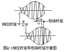
K is the transmission coefficient of the network, ψ, (ψ-Δψ), (ψ + Δψ) are the phase shift of the carrier frequency and the upper and lower side frequencies after passing through the network; ψ / ω2 is the delay of the carrier frequency component; ψ / ω1 is The envelope delay is shown in Figure Q-1.
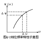
It can be seen that when the AM wave passes through the network, there are two delays of carrier frequency and envelope. However, it is not the phase delay that is closely related to the image quality, but the envelope delay. Because the envelope reflects the content of the transmitted signal. If the phase characteristic of the network is linear in the range of ω2 ± ω1, then although the envelope delay is generated, there is no envelope delay deviation. But in fact, the phase frequency characteristic of the network is always nonlinear, as shown in Figure Q-2. At this time, only a small segment of the phase characteristic curve can be regarded as linear in a very narrow frequency range. The slope of the straight line of this small segment is equal to the propagation time of the signal in this small frequency range. The mathematical expression is: τ = Δψ (ω2) / Δω2 Taking the limit of Δω2 → 0, we get:
τ = lim Δω2 → 0 [Δψ (ω2) / Δω2] = dψ (ω2) / dω2 At this time, τ represents the propagation time of the envelope of the composite signal in the infinitely narrow frequency band centered on ω2 through the network. Generally, since the envelope is composed of group frequency signals, the envelope delay is also called group delay.
Obviously, the group delay τ determined by dψ (ω2) / dω2 is the slope of each point of the phase-frequency characteristic curve shown in Figure Q-2, and is a function of frequency. The slope of the corresponding phase frequency characteristic curve at different frequencies is different, that is, the group delay values ​​are not equal. It is for this reason that the deviation between the group delay values ​​of the frequencies in the occupied frequency band is caused. The larger the deviation, the greater the distortion of the group delay of the reproduced image. Therefore, what we call group delay distortion refers to the deviation of this group delay. Thinking draft 2. Differential phase: Differential phase refers to the phase change of the color carrier component caused by the change of the luminance signal amplitude related to chroma. In the NTSC system, the change of the color signal vector angle represents the change of the hue, so the effect of the differential phase on the signal is very serious. The PAL system uses the line-by-line inversion technique, so the self-compensation effect causes the change in color saturation to replace the change in hue. In general, differential phase is a parameter used to describe the effect of changes in the amplitude of the luminance signal on the color tone. Thinking Draft 3. Differential Gain: Differential gain refers to the functional relationship between the change of the amplitude of the chrominance signal and the change of the amplitude of the related luminance signal. Its influence on the image is the change of the color saturation. Simply put: Differential gain is the effect of changes in the brightness signal amplitude on color saturation.

Follow WeChat
Interesting and informative information and technical dry goods

Download Audiophile APP
Create your own personal electronic circle

Follow the audiophile class
Lock the latest course activities and technical live broadcast
comment
Publish
related suggestion
Half-wave rectifier circuit 
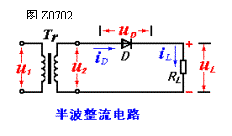
1. Half-wave rectifier circuit The half-wave rectifier circuit is shown in Figure Z0702. It consists of power transformer Tr rectifier diode D and load resistance RL ...
Posted at 2006-04-16 23:12 • 5988 views

Analysis of matched connection of half-wave symmetrical oscillator 
Analysis of matched connection of half-wave symmetrical oscillators ...
Posted at 2006-04-16 20:04 • 531 views

[Photo] Assembly and connection of half-wave dipole antenna ![[Photo] Assembly and connection of half-wave dipole antenna](http://i.bosscdn.com/blog/20/06/41/521650586.gif)
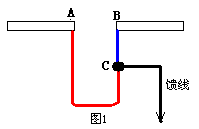
Matching of half-wave symmetrical oscillator and feeder ...
Posted at 2006-04-15 21:06 • 793 views
![[Photo] Assembly and connection of half-wave dipole antenna](http://i.bosscdn.com/blog/20/06/41/521650586.gif)
