Abstract: A distributed health monitoring system is designed for the safety monitoring needs of a certain network frame. The scheme of using a controller area network (CAN) to form a distributed communication network module in a distributed system is introduced. The design scheme of the acquisition system based on the CAN bus controller SJAl000 and the specific hardware circuit design are elaborated in detail, and the problems that are easily encountered in the software design are solved.
In a building with a large grid structure, due to the particularity of the grid structure and its geographical location in the coastal typhoon-prone zone, it is necessary to design a high-speed data collection system to monitor the health of the grid structure in real time and the data Perform real-time analysis and evaluation. Due to the need for multi-point monitoring of the stress on the grid, considering the poor expansion of the centralized control of the hardware and the difficulty of wiring in the field construction, this system uses the currently widely used distributed system design scheme to control each control The units are distributed on the collection points on site. In order to realize the monitoring and control functions of the distributed system, it is necessary to establish a good communication method to complete the information exchange and communication between the system host and each intelligent unit. According to the characteristics of this data collection system, its communication system should have good reliability, adaptability, scalability and simple connection, and can meet the needs of long-distance transmission. Due to the large number of nodes in this data acquisition system (100 channels), high requirements for signal transmission speed and low bit error rate, the traditional method of building a data acquisition system using the 485 bus can only have 32 maximum control nodes, which exceeds lkm The transmission speed of the wiring structure is only 100kbps, and the problems of "data collision" and "deadlock" are not easy to solve, so the use of the 485 bus obviously fails to meet the design requirements. 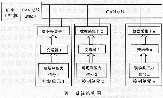
Compared with the traditional 485 bus, the controller area network CAN (Controller Area Network) as a kind of field bus, with its time-sharing multi-master, non-destructive bus arbitration and automatic error detection and retransmission and other flexible and reliable communication technology Solve the problems of 485 bus field debugging difficulties, long development cycle and so on [1]. Especially in the more difficult installation environment, its efficient on-site debugging performance is particularly practical. As a decentralized, digital, bidirectional, multi-point, high-speed and high-reliability communication system, CAN can build a flexible multi-master communication mechanism or a master-slave structure, and the hardware physics in these two ways The connection is exactly the same. The functions of automatic data encoding, CRC redundancy check, and automatic retransmission of errors ensure the accuracy of the data. When a certain node makes a serious error, it can automatically leave the bus to ensure the stability of the system, and it has a very strong load The capacity can drive up to 110 nodes, which can meet the requirements of high speed, precision and multiple loads of this system. 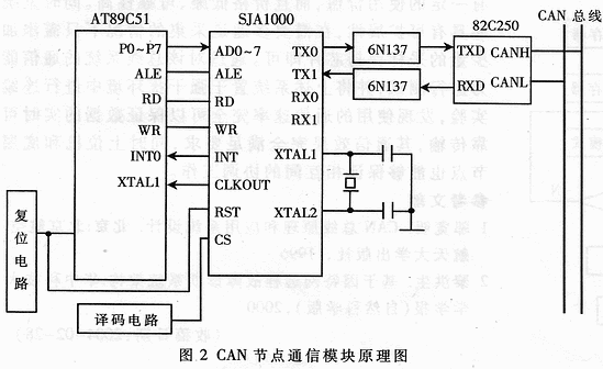
1 Design of the hardware circuit of the capture card
1. 1 CAN bus distributed system structure design
The system structure is shown in Figure 1. This system is controlled by the host PC, 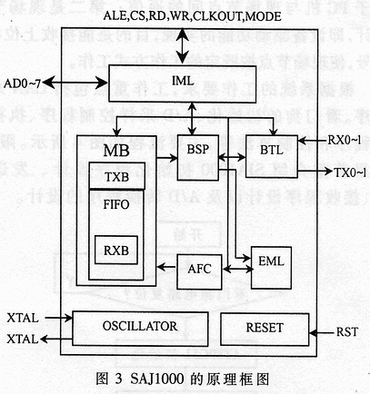 The CAN bus adapter card and control unit are composed of three parts. The upper monitoring PCs use IBM-PC compatible machines, which are mainly responsible for receiving and managing system data, sending control commands, and real-time display of dynamic parameters and device status of each control unit; the CAN bus adapter card can make the PC easily connect To the CAN bus; the control unit takes the single chip as the core, which is mainly responsible for monitoring the environmental parameters and equipment status of the site, packaging the collected data and sending the processed digital signals to the CAN bus through the CAN communication controller SJA1000 .
1.2 Module design of control unit and solution of key problems
The main function of the control unit is to convert the analog signals collected in the field into digital signals, which are processed by the CPU and then packaged by the CAN bus controller and sent to the CAN bus for the host computer to receive and process; receiving the control signals of the host computer to realize the specific operations of the field control . The specific problems to be solved are: â‘ CAN module design; â‘¡ A / D module design.
1. 2. 1 CAN module design
The control unit takes the 8-bit single-chip AT89C51 as the core, selects the device SJA1000 as the CAN controller, and selects the chips 82C250 and 6N137 as the CAN controller interface and optocoupler isolation. The hardware circuit is shown in Figure 2.
The CAN bus communication controller SJA1000 adopted by the system is an independent CAN device produced by PHILIPS, and its functional block diagram is shown in FIG. 3. It and CAN2. OB is compatible with [1], and supports 11-bit (BasicCAN mode) and 29-bit (PeliCAN mode) identification codes.
The ALE, WR, and RD terminals of the AT89C51 single-chip microcomputer in Figure 2 respectively control the ALE / AS, WR, and RD terminals of the SJA1000, and the address and data lines ADO to AD7 are realized by time-multiplexing of the P0 port. SJA1000's interrupt request signal INT jumps to a low level from high power when the interrupt is allowed and an interrupt occurs, so INT is directly connected to INT0 of AT89C51. The chip selection signal CS is controlled by the GAL decoding circuit. When CS receives the low level, the SJA1000 is selected, and the CPU can perform read / write operations on the SJA1000. In order to enhance the anti-interference ability of the control node and prevent crosstalk between lines, the SJA1000 is connected to the 82C250 through the optocoupler 6N137, thereby isolating each CAN node on the bus to protect the CAN controller from working properly. 82C250 is a CAN bus transceiver, which is an interface device between the CAN controller SJA1000 and the CAN bus, and sends it to the CAN bus in a differential manner. Its pin RS is used to select the working mode of 82C250 (high speed, slope control or wait). RS pin is grounded, 82C250 works in high-speed mode, RS pin is connected in series with a resistor R and then grounded. If 82C250 is in the network terminal of CAN bus, the bus interface part must add a 120Ω matching resistor to protect 82C250 from overcurrent impact . 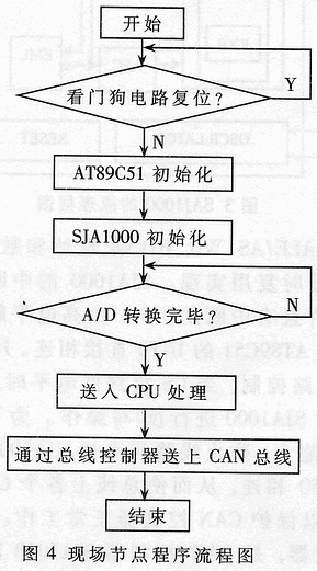
1.2.2 A / D module design
The A / D chip selects the 12-bit high-speed acquisition chip AD574. In this design, the function of the A / D module is to convert external analog signals into digital signals through AD574 and input them in parallel to AT89C51, then AT89C51 packs them and outputs them in parallel to the CAN bus communication controller SJA1000, and to CAN through the bus transceiver bus. Its monitoring circuit adopts DS1232, which has power monitoring, manual reset and watchdog functions, and can also output two high and low level reset signals at the same time, respectively output to the reset terminal of AT89C51 and SJA1000, to meet the requirements of this design.
2 Software design
This health monitoring system requires that the software part has the functions of on-site digital signal display, detection and driving of on-site signal equipment. In this design, two main tasks are completed: the first is the upper computer display of the PC part, the upper computer monitoring and display interface is mainly designed through the integrated development environment software, and its focus is on the communication between the PC and the site nodes; the second is The design of field node control, that is, the realization of the device driving function, the purpose is to be able to receive the control signal of the host computer, so that the field node works according to the established working mode.
According to the work requirements of the system, the focus of work includes CAN bus communication procedures, watchdog initialization, A / D sampling control procedures, actuator control procedures and control algorithms. The main flow is shown in Figure 4. Due to space limitations, I will focus on the introduction of SJA1000 initialization programming, sending programming, receiving programming and A / D conversion program design.
2. 1 SJA1000 initial design
The initialization flow chart is shown in Figure 5. After the AT89C51 is powered on or reset, the reset program is called to provide a reset signal to the reset terminal (RST) of the SJA1000, so that the SJA1000 enters the reset mode. The initialization of SJA1000 can only be performed in reset mode. The initialization program mainly completes the design of the following registers: (1) Through the definition of the clock divider register of SJA1000, determine whether to use the BasicCAN mode or the PeliCAN mode; whether to enable CLOCKOUT and output clock frequency; whether to use the bypass CAN input comparator; Whether the TX1 output uses a dedicated receive interrupt. (2) Define the acceptance code of the received message by writing the acceptance code register and the acceptance mask register, and define the acceptance mask code by comparing the relevant bits of the message and the acceptance code. (3) Define the bit rate of the bus, the sampling points within the bit period, and the number of samples within one bit period by writing the bus timing register. (4) Define the output mode and output configuration of the CAN bus output pins TX0 and TX1 by writing the output register. (5) Clear the reset request flag of SJA1000 and enter the normal working mode, so that SJA1000 can send and receive messages.
2.2 Send and receive programming
The MCU sends the message to be sent to the send buffer of the SJA1000, and then sets the send request flag (TR) of the SJA1000 command register, and the sending process is independently completed by the SJA1000. Before a new message is written to the transmit buffer, the status flag bit (TBS) of the transmit buffer of the status register must be checked. If it is "1", the transmit buffer is released and the new message can be written to the transmit buffer Otherwise, the send buffer is locked and new messages cannot be written. The sending program can use the interrupt mode and query mode. In this design, the query method is used.
The reception of the message is also completed independently by SJA1000. The received message is stored in the FIFO through the receive filter. The first message enters the receive buffer and is marked by the receive buffer status flag bit (RBS) and receive interrupt flag bit (RI) of the status register. After the MCU takes a message from the receive buffer, it must release the receive buffer by setting the SJA1000 command register. In this design, the design of the receiving program uses the interrupt mode. 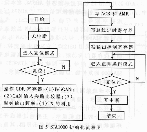
2. 3 A / D conversion design
What is adopted in this design is 12-bit successive approximation type A / D converter AD574. Design the program by querying, and determine whether the conversion is completed by continuously querying the A / D conversion end flag. When the conversion is completed, the data is sent to the CPU for processing, and the processed data is saved to the 6264 chip.
The high-speed distributed data acquisition system based on CAN bus design has certain use value, and it is low in price and high in reliability. At the same time, the system is also extensible, and only a small number of sample-and-hold chips need to be added when multi-channel acquisition is required. By testing the communication capability of the bus system, and placing the above system in a strong interference environment for continuous experiments, it was found that the communication rate used can fully guarantee the real-time and reliable transmission of data, and its communication effect fully meets the requirements. The underlying nodes can also ensure coordination between each other.
Digital Signage,Digital Screen Poster,Android Video Players,Digital Signage Display Screen
ALLIN , https://www.displayapio.com
